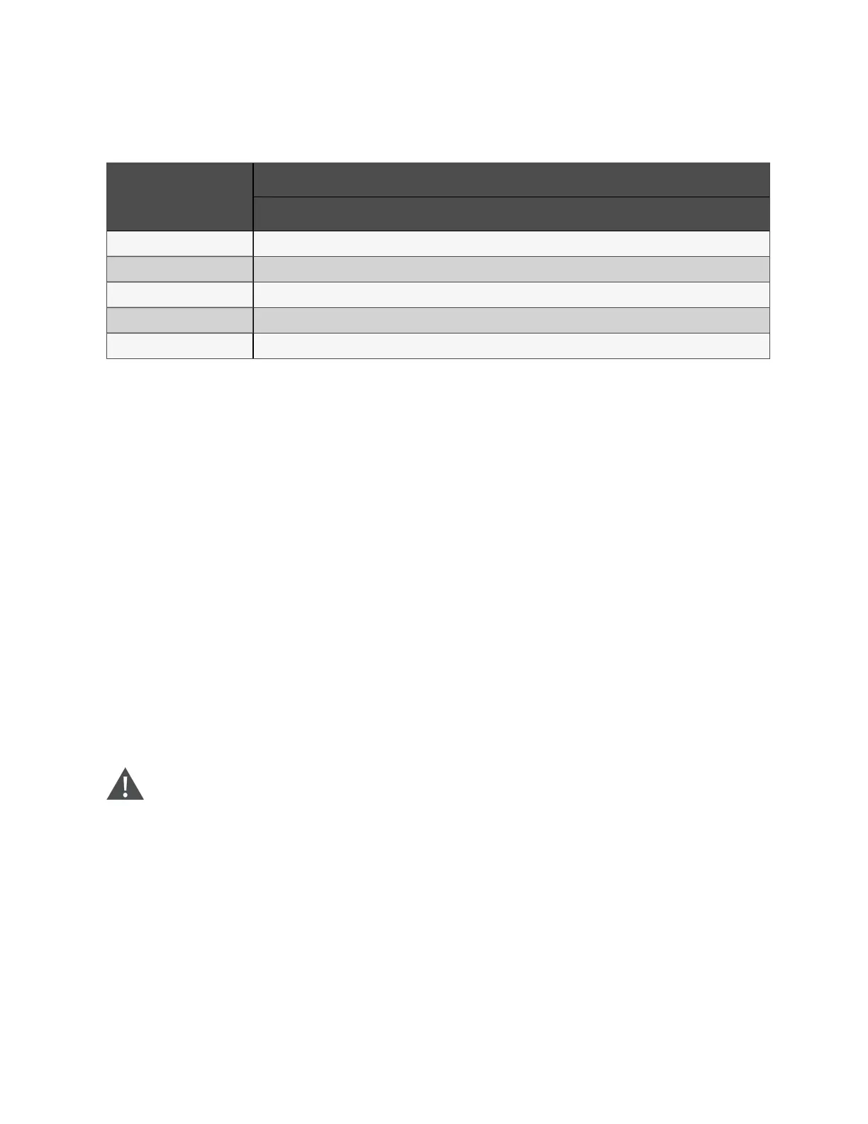
4.1.5 Distance between the UPS Connection Point and Floor
UPS con nectio n po int
M in. d istance (m m )
25 0 kV A
Rectifier input 348
Bypass input 387
AC Output 371
Battery supply 425
PE terminal 510
Table 4.4 M in. distance betw een UPS connectio n point and floor
4.1.6 Notes
The following points are for general guidance only. If there are relevant local regulations, the local regulations shall prevail.
1. The cable size of the protective earth cable shall be selected according to the AC power failure level, cable
length, and protection type. The grounding wire connection must use the shortest connection route.
2. For the cables with large current, parallel connection of small cables can be adopted to facilitate the installation.
3. When selecting the battery cable size, the current value in Table 4.1 on the previous page shall be referred to,
and a maximum voltage drop of 4 Vdc is allowed.
4. Do not form coils, so as to minimize the formation of EMI.
4.1.7 Power Cable Connecting Terminal
The rectifier input, bypass input, output and battery power cables are connected to the corresponding terminals shown in
Figure 4.2 on page33.
4.1.8 Protection Ground
The protective earth cable is reliably connected to the PE input terminal (see Figure 4.2 on page33) via the fixing bolt. All the
cabinets and cable troughs shall be grounded according to the local regulations. The grounding wires shall be tied up reliably
to prevent the loosening of the grounding wire tightening screws when the grounding wires are pulled.
W ARN ING ! F ailure to g round as required may cau se E M I, electric shock, or fire risk.
4 Electrical Installation
30
Vertiv™ Liebert® APM Plus User Manual