4.2.3 Dry Contact Port J7
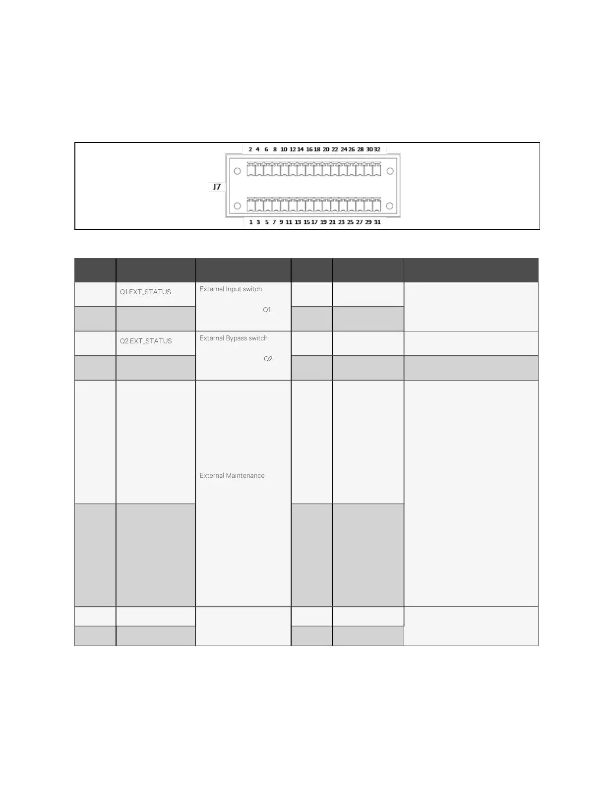
The dry contact port J7 is shown in Figure 4.6 below and described in Table 4.6 below.
Figure 4.6 D ry contact port J7
Pin N am e M eanings P in Nam e M ean ing s
1 Q1 EXT_STATUS
External Input switch status
(24 V/ 10 mA rated);
Pin1/Pin3 shorted for Q1 EXT
closed
2 GEN_MODE
Generator mode (24 V/10 mA rated).
Pin2/Pin4 shorted for generator
connected
3 GND_DRY 4 GND_DRY
5 Q2 EXT_STATUS
External Bypass switch
status (24 V/10 mA rated);
Pin5/Pin7 shorted for Q2 EXT
closed
6 TMP_BATT_IN Internal battery temp (analog signal)
7 GND_DRY 8 +12 V_DRY +12 V Power
9 QBP_STATUS
External Maintenance switch
status (24 V/10 mA rated);
Pin9/Pin11 open for QBP
closed
10
Configurable input
dry contact 1 J7-
10/12
Inverter status (24 V/10 mA rated);
available when pin10/12 opened.
0) Undefined
1) Battery fault
2) External maintenance isolation switch
closed
3) ECO mode disabled (default)
4) Charger to be shut down
5) BCB tripping
6) Transfer to inverter disabled
7) Battery maintenance self-check starts
8) Battery maintenance self-check ends
9) Alarm cleared
10) Battery alarm
11) Battery low-voltage alarm
11 GND_DRY 12 GND_DRY
13 QE_STATUS
Output switch status (24
V/10 mA rated); Pin13 /Pin15
shorted for QE closed
14 ENV_DET
Battery room temperature status (24 V/10
mA rated). Pin14/Pin16 shorted for battery
room temperature abnormal
15 GND_DRY 16 GND_DRY
Table 4.6 D escrip tion of dry contact port J7
4 Electrical Installation
39
Vertiv™ Liebert® APM Plus User Manual