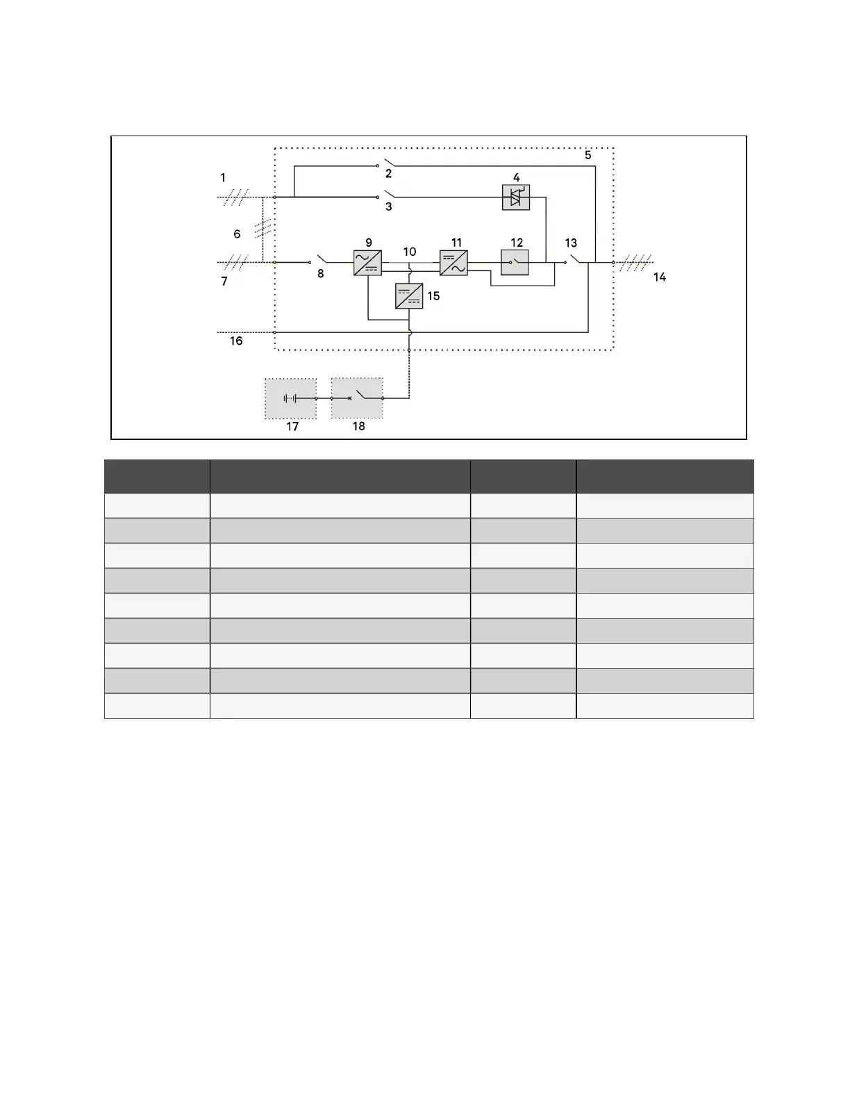
Figure 2.2 UPS pow er supply sw itch configuration
N o. Descriptio n N o. Description
1 Bypass input 10 DC bus
2 Maintenance bypass switch Q3 11 Inverter
3 Bypass input switch Q2 12 Inverter switch
4 Static switch 13 Output switch Q5
5 UPS 14 UPS output
6 Shorting copper bar of input configuration 15 Charger
7 Mains input 16 Neutral line input
8 Rectifier input switch Q1 17 Battery
9 Rectifier 18 BCB
N O T E: Q1, Q2 and Q5 are optional w hile Q3 is standard
N O T E: The m ains inp ut an d bypass input share the sam e neutral lin e.
2.2.5 Battery Circuit Breaker (BCB)
The external battery shall be connected to the UPS through the BCB. The BCB cabinet is optional, which shall be installed
near the battery. The BCB is closed manually. The BCB has a shunt tripping coil. When the system is faulty and the BCB
needed to be disconnected, the UPS control circuit will send a signal to the shunt tripping coil so as to trip the BCB. It also has
a magnetic trip facility for overload protection and short circuit protection.
2 Overview
6
Vertiv™ Liebert® APM Plus User Manual