Service procedures of parallel system in normal mode
1. Confirm that there is power redundancy after disconnecting the UPS to be maintained, to avoid output overload.
2. Press the EPO button for the UPS to be serviced, and open the mains input switch, bypass input switch, and
output switch.
3. Place the ready switch on the front panel of the power module to unready state.
4. Remove the fixing screws on both sides of the front panel of the bypass power module, unplug the signal cables
and pull the module out of the cabinet, then maintain the module.
5. After servicing the module, push the module into the cabinet, and tighten the screws on both sides.
6. Close the mains input switch, bypass input switch, output switch, and BCB. Place the ready switch to ready state.
Then start the system following the procedures in Procedures for Inserting One Isolated UPS module in Parallel
System.
11.3 Key Components and Service Life of UPS
When in use, some devices of UPS system will have shorter service life than UPS itself due to abrasion in work. For the safety
of UPS supply system, it is necessary to have regular inspection and replacement of these devices. This section introduces
the key components of UPS and the reference years of service life. For systems under different conditions (environment, load
rate, and etc.), assessment and advice by professionals on whether to replace the device are required with reference to the
information provided in this section.
11.3.1 Life Parameters and the Proposed Replacement Time of Key Components
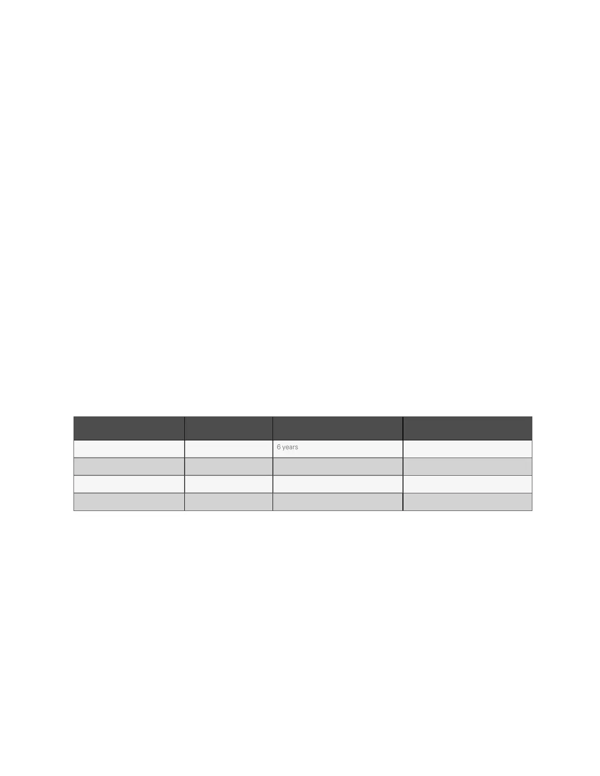
Key components in Table 11.1 below are used in the UPS system. To prevent system failures due to some of the devices' failure
by wear, it is proposed to carry out regular inspection and replacement during its estimated life.
Key co m p onents Es tim ate d life Pro posed replacem en t tim e P ropo se d insp ection period
Fan Not less than 7 years 6 years 1 year
Air filter 1 year to 3 years 1 year to 2 years 2 months
VRLA battery (5-year life) 5 years 3 years to 4 years 6 months
VRLA battery (10-year life) 10 years 6 years to 8 years 6 months
Table 11.1 Life p aram eters an d the proposed replacem ent tim e of key com p onents
11 Service and Maintenance
168
Vertiv™ Liebert® APM Plus User Manual