4.2.2 Dry Contact Port J6
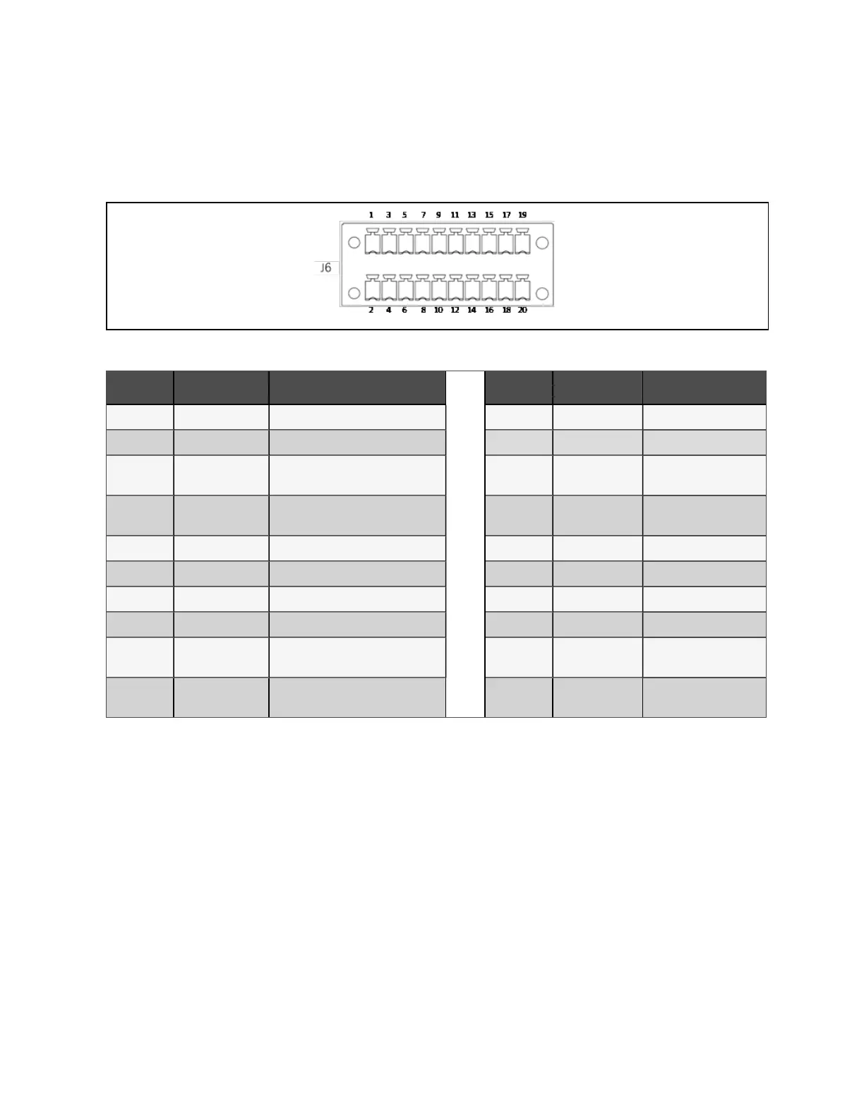
The dry contact port J6 is shown in Figure 4.5 below and described in Table 4.5 below.
Figure 4.5 D ry contact port J6
Pin N am e M eanings Pin N am e M eanings
1 +12V BCB drive signal (12V) 2 PARA_CAN_H Parallel CAN1
3 BCB_STATUS BCB state signal (24V, 10mA) 4 PARA_CAN_L Parallel CAN1
5 GND_DRY Dry ground 6
PARA_Mon_CAN_
H
Parallel CAN2
7 BCB_ONLine BCB on line signal 8
PARA_Mon_CAN_
L
Parallel CAN2
9 PE PE 10 Para_SER_BUS_H Parallel CAN3
11 GND_DRY Dry ground 12 Para_SER_BUS_L Parallel CAN3
13 TMP_BAT Reserved 14 NA Not available
15 12V_DRY Power 16 PE PE
17 GND_DRY Dry ground 18 battery_CAN_H
Battery communication
CAN_H
19
BAT_Ground_
FAULT
Battery ground fault (24V, 10mA) 20 battery_CAN_L
Battery communication
CAN_L
Table 4.5 D escriptio n of dry contact port J6
N O T E: The B C B cable of J6 must be shielded with w ire braid, and the shield cab le connected to the
UPS term inal can b e earthed to Pin9.
N O T E: Pin18, P in20 m ust be shielded d ouble stranded cable with wire braid, and Pin16 can be
conn ected to the shield wire grounding of UP S term in al.
N O T E: The B C B drive sig nal and external battery signal need shielded cables, and both ends of the
shielding layer m ust be reliably connected to the chassis.
4 Electrical Installation
38
Vertiv™ Liebert® APM Plus User Manual