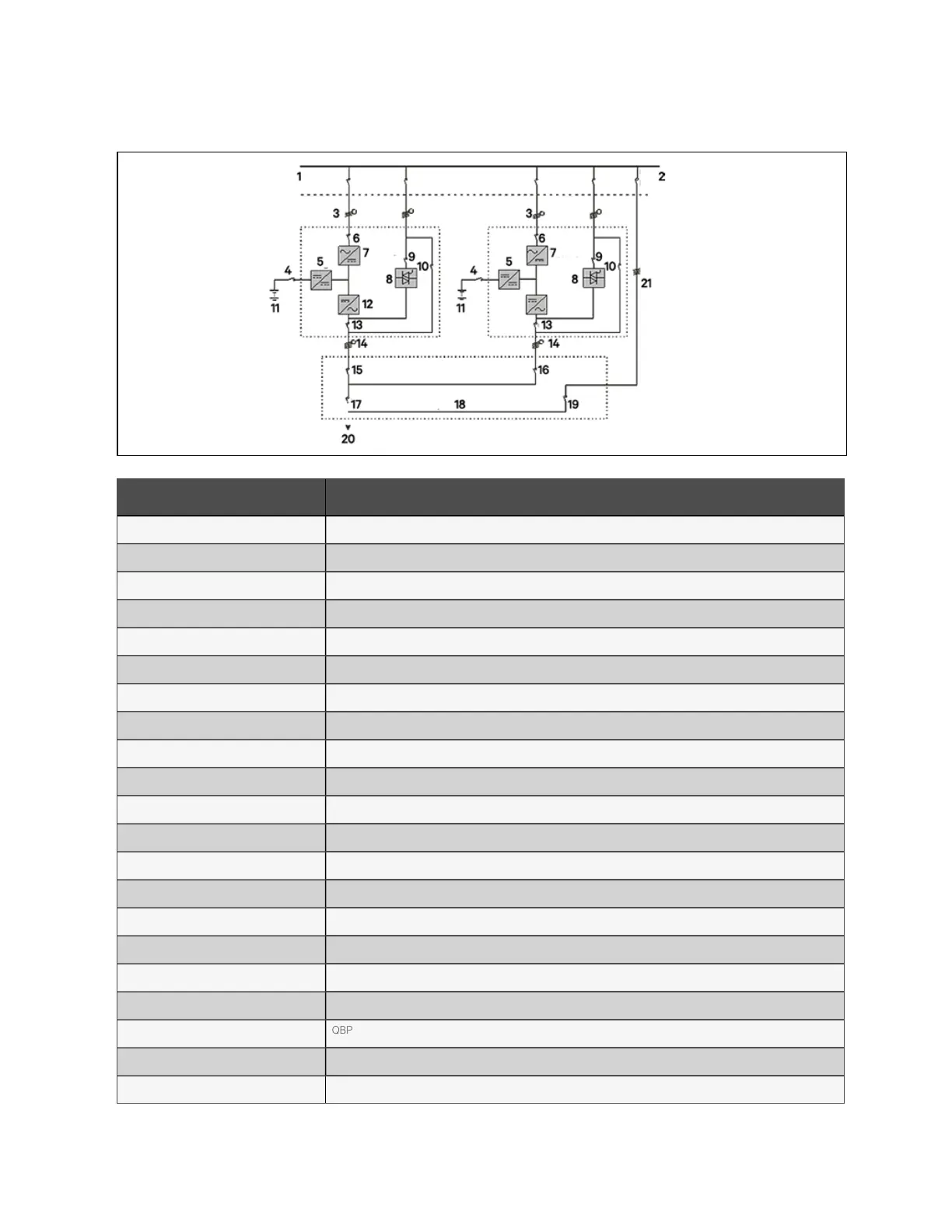
Figure 8.1 Schem atic of typical parallel system (w ith com m on input, separate batteries and outp ut)
N o. Descriptio n
1 Input power supply
2 External bypass switch
3 Mains input L1, L2, L3, N
4 BCB
5 Charger
6 Q1
7 Rectified
8 Static switch
9 Q2
10 Q3
11 Battery 1
12 Inverter
13 Q5
14 L1, L2, L3, N
15 Q1EXT
16 Q2EXT
17 QBP
18 Output distribution
19 QBP
20 To load
21 External maintenance bypass
N O T E: Q1, Q2, an d Q5 are optional while Q3 is standard .
8 Parallel System and LBS System
129
Vertiv™ Liebert® APM Plus User Manual