Vertiv™ NetSure™ 5100 Series -48 VDC Power System Installation Manual
Proprietary and Confidential © 2023 Vertiv Group Corp.
5.13 External Alarm, Reference, Monitoring, and Control Connections
5.13.1 External Alarm, Reference, Monitoring, and Control Connection Locations
Refer to Figure 5.17, Figure 5.18, Figure 5.19.
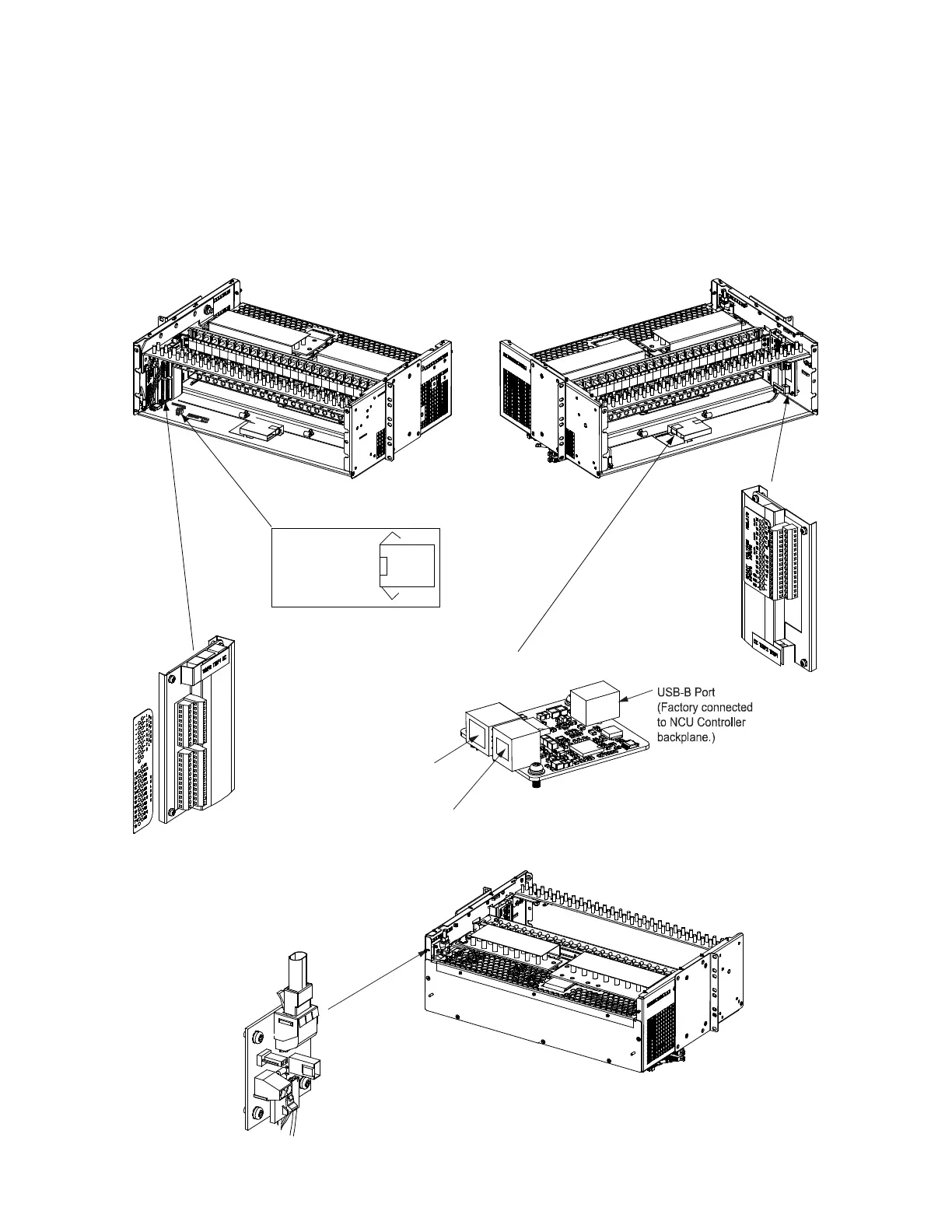
Figure 5.17 External Alarm, Reference, Monitoring, and Control Connections in a List 20, 25 Distribution Cabinet (see
proceeding pages for connection details)
IB2
(Controller
Interface Board)
Optional EIB
(Controller Extended
Interface Board)
Optional IB4 Board
10M Ethernet
Port (RJ-45)
LAN Connection
USB-A Port
(not used)
Front
Front
Components removed in
illustration for clarity.
Rear
System
Interface
Board
1 RS485A
2 RS485B
3 CGND
RS485 MODBUS
CONNECTION

 Loading...


