Vertiv™ NetSure™ 5100 Series -48 VDC Power System Installation Manual
Proprietary and Confidential © 2023 Vertiv Group Corp.
6 Installing the Modules
6.1 Installing Rectifier, Solar Converter, and Converter Modules
Rectifier, solar converter, optional -48 VDC to +24 VDC converter modules, and optional -48 VDC to -58 VDC converter modules can
be inserted or removed with power applied (hot swappable).
Procedure
NOTE!
Each module locks into the module mounting assembly by means of a latch located on the bottom of the module.
The latch and module handle are interactive. Pushing the handle up into the module’s front panel causes the latch to extend
to the locking position; pulling the handle down out from the module’s front panel causes the latch to retract. See Figure 6.3,
Figure 6.4, or Figure 6.5.
NOTE!
For systems using an AC feed option where each feed connects to two (2) slots in the shelf (List 46 or Molex
connected cords) and -48 VDC to +24 VDC converters or -48 VDC to -58 VDC converters are being used (List 26 two row
distribution panel or List 27 single row distribution panel) in the plant, the following module restrictions apply for factory
installed shelves 2 through 5:
o Rectifiers can be in any or all six (6) positions if three (3) AC inputs provided.
o +24V or -58V converters can be in the right three (3) positions (positions 4, 5 and 6).
o Rectifiers can be in any position which has AC power that is not taken up with a converter.
o One (1) Solar converter can be installed in the shelf, position 1 or 2.
o Three (3) solar converters can be installed in the shelf, positions 1 or 2, positions 3 or 4 and positions 5 or 6 if the -48V
to +24V or -48V to -58V bus bar is not installed to the shelf above.
WARNING! To prevent damage to the latching mechanism, ensure the handle is in the open position when installing or
removing a module. NEVER hold the handle in the closed position when installing a module into a module mounting
assembly.
ALERT! The system can either have +24V DC-DC converters installed or -58V DC-DC converters installed. The system
cannot have both types of converters installed at the same time.
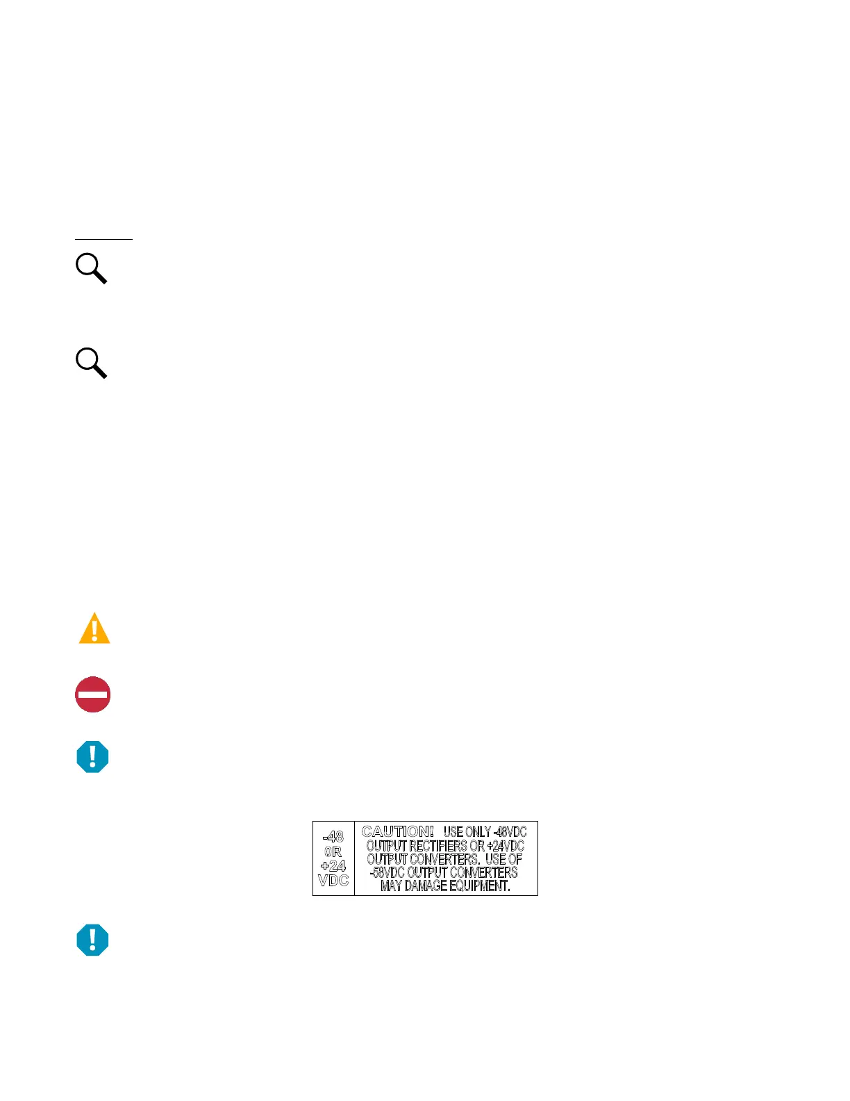
ALERT! The -48 VDC to +24 VDC converter modules must only be installed in a system position that accepts a +24V DC-DC
converter. Refer to labeling on the system’s module mounting shelf. A sample of this labeling is provided in Figure 6.1.
Figure 6.1 Sample Module Mounting Shelf Labeling
ALERT! The -48 VDC to -58 VDC converter modules must only be installed in a system position that accepts a -58V DC-DC
converter. Refer to labeling on the system’s module mounting shelf. A sample of this labeling is provided in Figure 6.2.

 Loading...


