Vertiv™ NetSure™ 5100 Series -48 VDC Power System Installation Manual
Proprietary and Confidential © 2023 Vertiv Group Corp.
5.15 Control Bus Connections between Controller and Module Mounting
Assemblies
General
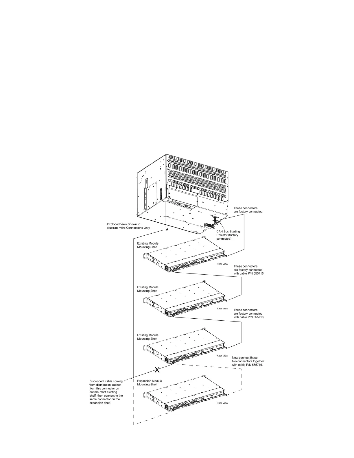
Each module mounting assembly in the system is daisy-chained to the controller. NCU CAN bus connectors are located at the left
and right rear of each module mounting assembly. These connectors are used to interconnect the module mounting assemblies to
the controller and to other module mounting assemblies.
The right side module mounting assembly NCU CAN bus connector is factory jumpered so both connectors can be accessed from the
left side of the module mounting assembly. Refer to Figure 5.30 for connector locations and an interconnect diagram. These
connections are factory made for module mounting assemblies factory installed. For field expansion, the new module mounting
assembly must be tied into the interconnect scheme as shown in Power System User Instructions UM582137100.
Figure 5.30 Control Bus Connections between Controller and Module Mounting Assemblies

 Loading...


