Vertiv™ NetSure™ 5100 Series -48 VDC Power System Installation Manual
Proprietary and Confidential © 2023 Vertiv Group Corp.
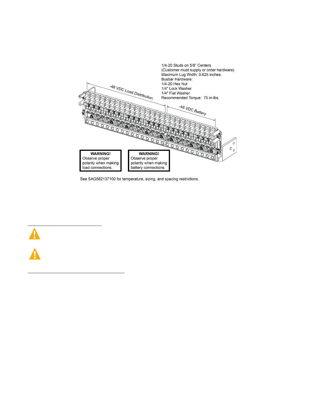
Figure 5.75 List BD Battery Connections in a List 26 Distribution Cabinet
(16) -48 VDC Load Bullet/TPS/TLS Circuit Breaker/Fuse Positions and
(10) -48 VDC Battery Disconnect Bullet/TPS/TLS Circuit Breaker/Fuse Positions
5.19.3 Input Battery Connections to List 27 Distribution Cabinet
Refer to the following.
Important Safety Instructions
DANGER! Adhere to the “Important Safety Instructions” starting on page vii.
WARNING! Observe proper polarity when making output connections.
To Battery and Battery Return Busbars
Input battery leads are connected to the battery (load side) busbar and battery return busbar. Refer to Figure 5.76 for connection
details and recommended torque.
5.20 Remote Distribution Unit (DU) Connections
5.20.1 List 27 Distribution Cabinet
Remote Distribution Unit (DU) input leads are connected to the remote DU input busbar and battery return busbar. Refer to
Figure 5.76 for connection details and recommended torque.

 Loading...


