Vertiv™ NetSure™ 5100 Series -48 VDC Power System Installation Manual
Proprietary and Confidential © 2023 Vertiv Group Corp.
• SOLAR: If you have only solar converters in the system, set Solar Mode to “SOLAR”. Also set the “Float Charge Voltage
(Solar)” parameter to the desired float setting.
NOTE!
When solar converters are all installed prior to applying power and starting system, the NCU will NOT communicate
with solar converters until SOLAR MODE is enabled.
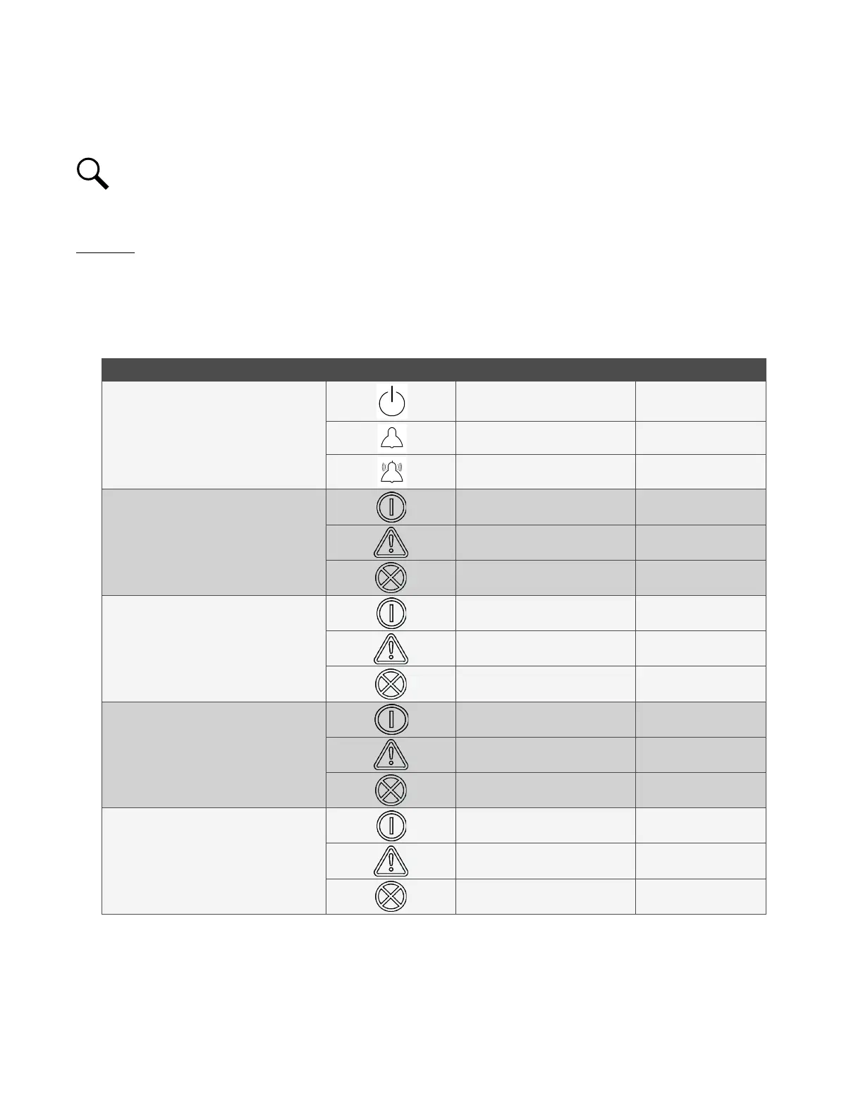
7.6 Checking System Status
Procedure
1. Observe the status of the indicators located on the controller, rectifiers, solar converters, -48 VDC to +24 VDC converters or
-48 VDC to -58 VDC converters (if furnished), and inverters (if furnished). If the system is operating normally, the status of
these is as shown in Table 7.2.
Table 7.2 Status and Alarm Indicators
Component Indicator Normal State
NCU
Status (Green) On
Minor Alarm (Yellow) Off
Critical or Major Alarm (Red) Off
Rectifier
Modules
Power (Green) On
Protection (Yellow) Off
Alarm (Red) Off
Solar
Converter
Modules
Power (Green) On
Protection (Yellow) Off
Alarm (Red) Off
-48 VDC to
+24 VDC Converter Modules and
-48 VDC to -58 VDC Converter Modules
Power (Green) On
Protection (Yellow) Off
Alarm (Red) Off
Inverter Modules
Power (Green) On
Protection (Yellow) Off
Alarm (Red) Off

 Loading...


