Vertiv™ NetSure™ 5100 Series -48 VDC Power System Installation Manual
Proprietary and Confidential © 2023 Vertiv Group Corp.
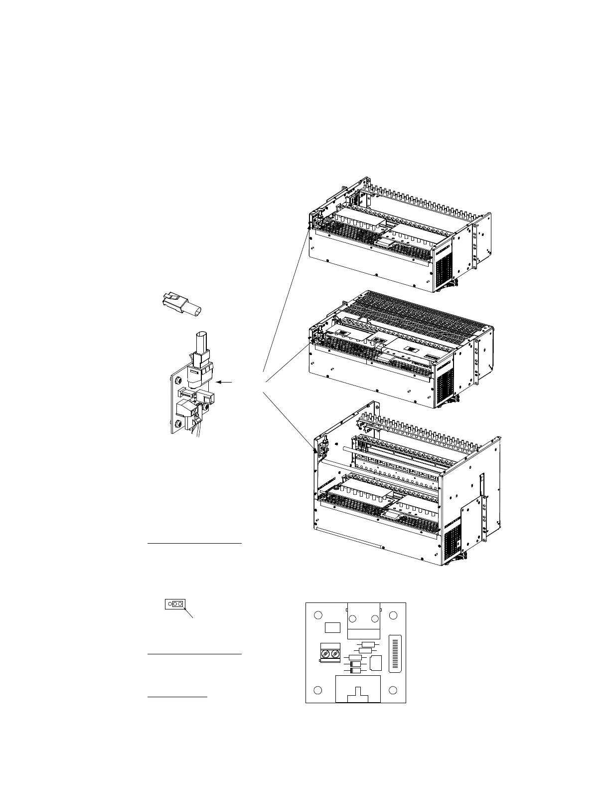
5.13.2 System Interface Circuit Card Connections (if required)
The system interface circuit card provides connections for the following. Refer to Figure 5.20 for circuit card location and connections
details.
• RS-485 (used for communication with SM modules)
Figure 5.20 System Interface Circuit Card Connections
Rear
Rear
R
ear
List 20, 25
List 27
List 21, 26
System
Interface
Board
J2 Controller
CAN Port (RJ-45)
A CAN termination plug
(P/N 548398) must be
installed if an external
device or system is not
connected here.
System Interface Board P/N 555484
J3 on System Interface Board
Wire Size Capacity: 16 AWG to 30 AWG.
Wire Strip Length: 0.32 inch.
Recommended Torque: 2.3 in-lbs.
RS485 Connection
J3-1: RS485+
J3-2: RS485-
J1
J2
J3
J4
J5
1
1
555484
0 0 0 X X X X X
A X X X X X X X X
1
No
Battery
P
wr
Battery
Pwr
Shorting
Jumper
J4 on System Interface Board
Selects to power controller
from “Battery Power” or not
if a battery LVD contactor is furnished.

 Loading...


