Vertiv™ NetSure™ 5100 Series -48 VDC Power System Installation Manual
Proprietary and Confidential © 2023 Vertiv Group Corp.
4.3 Switch Settings on the IB2 (Controller Interface Board)
Dip Switch SW1 on the IB2 board is used to set the communications address for this board. Refer to Table 4.1 for SW1 settings. Refer
to Figure 4.1, Figure 4.2, and Figure 4.3 for circuit card location. Refer to Figure 4.5 for SW1 location.
Perform the following procedure to verify the factory settings.
This procedure can also be used to make adjustments on a replacement circuit card.
Procedure
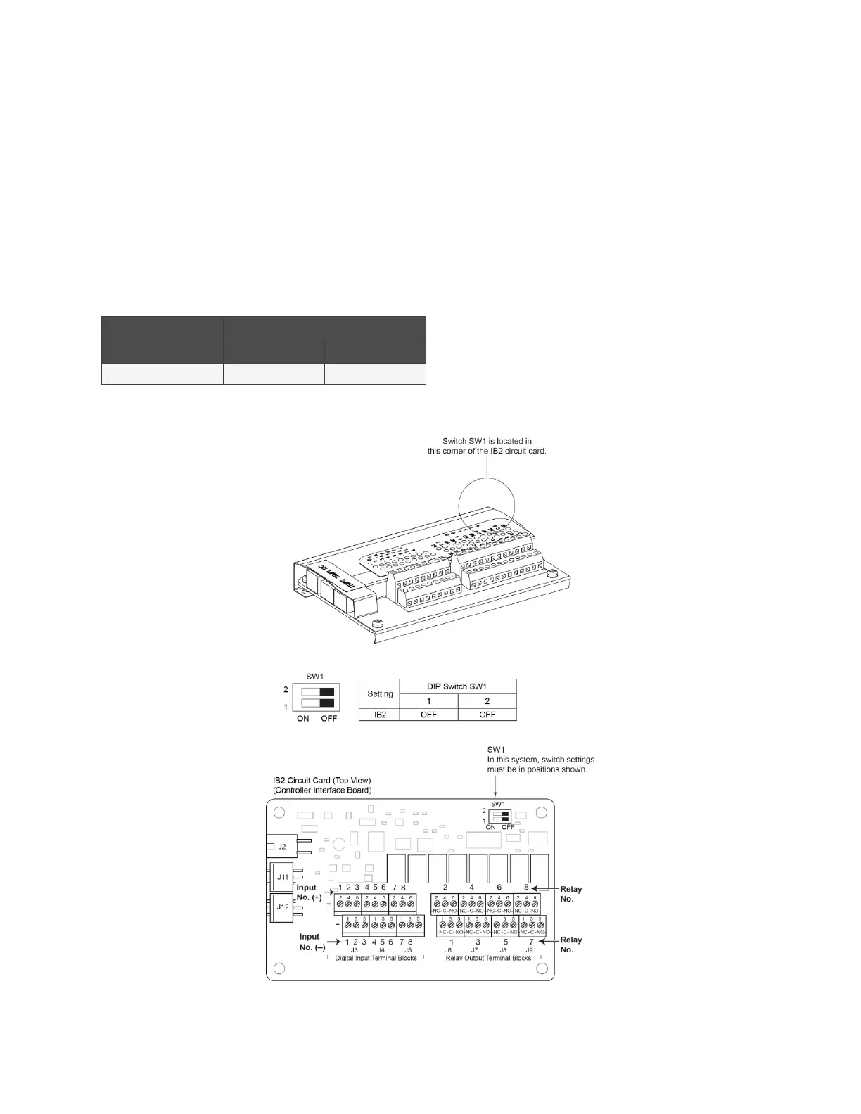
1. Ensure SW1 is set per Table 4.1. Refer to Figure 4.5 for location.
Table 4.1 IB2 Interface Board Switch Settings
Setting
DIP Switch SW1
1 2
IB2 OFF OFF
Figure 4.5 IB2 Interface Board Switch Location and Settings

 Loading...


