Vertiv™ NetSure™ 5100 Series -48 VDC Power System Installation Manual
Proprietary and Confidential © 2023 Vertiv Group Corp.
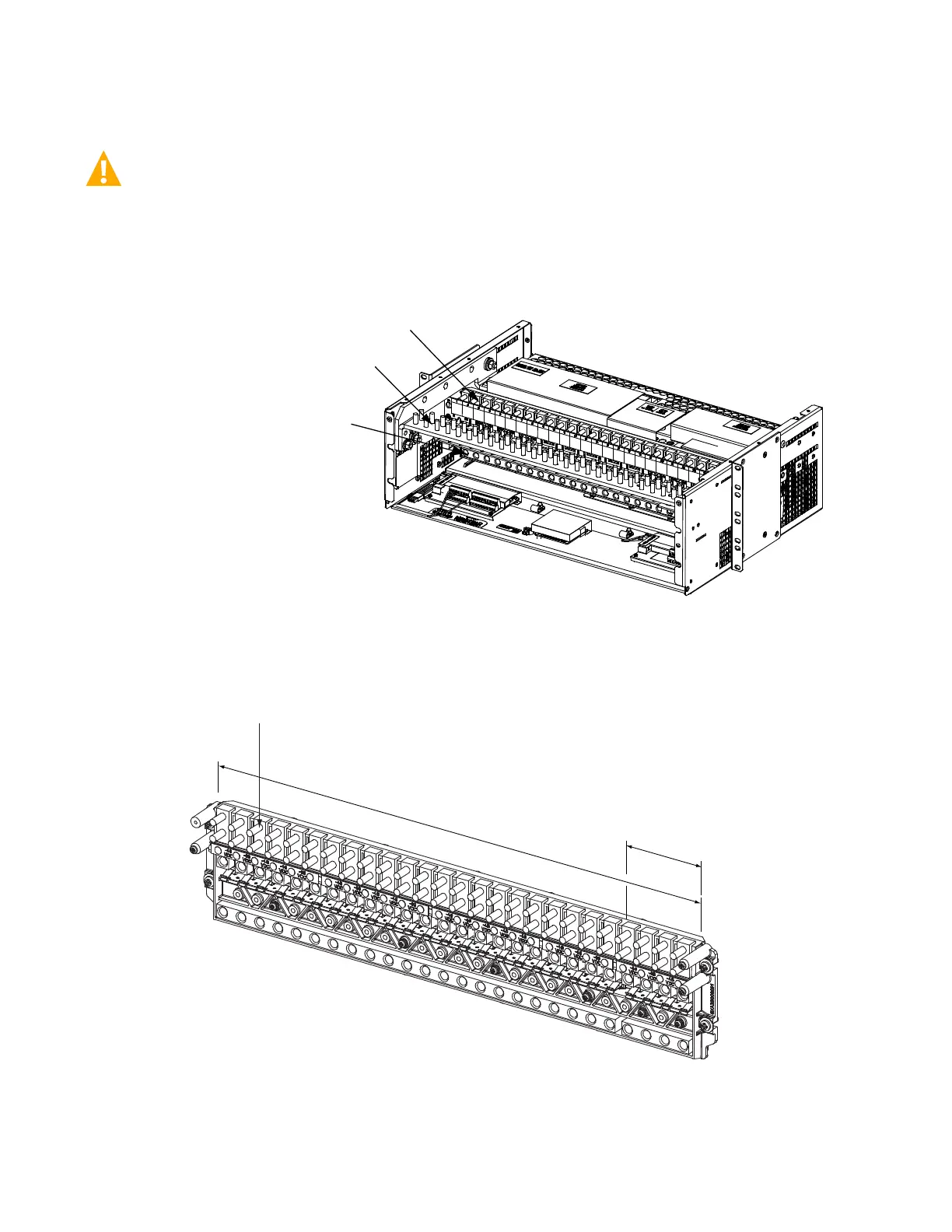
5.17.3 Load Connections to a List 27 Distribution Cabinet
WARNING! Observe proper polarity when making output connections.
Load leads are connected to the individual load busbar located on the distribution panel (refer to Figure 5.60). Load return leads are
connected to separate return busbar located at the top of the distribution cabinet (refer to Figure 5.61). Refer to Figure 5.62 for an
illustration of the available distribution panel. Torque connections as shown in the illustration.
Figure 5.60 Load Side Connections in a List 27 Distribution Cabinet
Distribution Row
Load Return Bus
(see next page)
Load Bus
Components removed in
illustration for clarity.
Distribution rows shown for sample only.
Other configurations available.
Front
1/4-20 Studs on 5/8” Centers
(Customer must supply or order hardware)
Maximum Lug Width: 0.625 inches.
Busbar Hardware:
1/4-20 Hex Nut
1/4" Lock Washer
1/4" Flat Washer
Recommended Torque: 75 in-lbs.
-48 VDC Distribution
Field Conversion to
+24 VDC Distribution
Possible These Positions
Load Connections
The distribution panel is shipped configured
with all -48 VDC distribution positions.
When using converter modules, you MUST
change the last four (4) positions to +24
VDC distribution positions in the field.
Refer to UM582137100 for a procedure.

 Loading...


