Vertiv™ NetSure™ 5100 Series -48 VDC Power System Installation Manual
Proprietary and Confidential © 2023 Vertiv Group Corp.
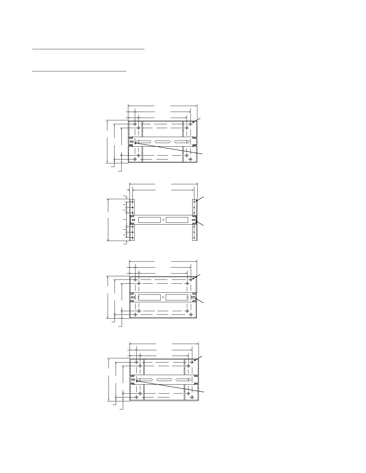
Relay Rack Floor Mounting Dimensions
Refer to Figure 3.1 and Figure 3.2 for relay rack floor mounting dimensions.
Optional Relay Rack Isolation Kit
Refer to Figure 3.3 when using the Optional Relay Rack Isolation Kit.
Figure 3.1 Relay Rack Floor Mounting Dimensions - 23” (cont’d on next page)
Part No. 543156
Part No. 543160
Part No. 543161, 543162,
543163, 543164
17.50
20.13
24.38
2.13
3.44
9.88
12.53
15.00
1.24
2.56
0.875 Dia.
(8 Places)
Masked for Frame Ground Lug
0.281 Dia. Holes on 0.625 Centers
(Top of Rack, 2 Places)
22.500
24.750
1.125
15.000
17.500
20.125
25.000
2.437
3.750
9.871
12.531
15.031
1.250
2.580
2.00
1.00
1.00
2.00
2.00
2.00
5.00
0.437 Dia.
(12 Places)
Masked for Frame Ground Lug
0.281 Dia. Holes on 0.625 Centers
(Top of Rack, 2 Places)
0.875 Dia.
(8 Places)
Masked for Frame Ground Lug
0.281 Dia. Holes on 0.625 Centers
(Top of Rack, 1 Place)
Part No. 541340
19.685
22.310
25.800
1.760
3.073
12.34
15.000
18.000
1.500
2.830
0.875 Dia.
(8 Places)
Masked for Frame Ground Lug
0.281 Dia. Holes on 0.625 Centers
(Top of Rack, 2 Places)

 Loading...


