Vertiv™ NetSure™ 5100 Series -48 VDC Power System Installation Manual
Proprietary and Confidential © 2023 Vertiv Group Corp.
5.13.8 Connecting a Device or System to the NCU CAN Bus (if required)
A supporting device or system may be connected to the NCU CAN Port located inside a distribution cabinet. Refer to Figure 5.20 for
location. Refer to Table 5.8 for pin-outs. Refer also to the external device’s or system’s instruction manual.
General Procedure
1. Remove the CAN termination plug from the CAN Port connector (see Figure 5.20 for location). Connect the device or system
to the NCU Controller’s CAN port. Refer to Table 5.8 for pinouts. Ensure that the last device on the controller’s CAN bus has
a CAN termination plug. Refer also to the external device’s or system’s instruction manual.
Optional SM-Temp Module Procedure
The analog output of the SM-Temp Module may be connected to an NCU temperature port input. In lieu of connecting the analog
output of the SM-TEMP module to an NCU temperature port input, the SM-TEMP module can simply be connected at the end of the
NCU CAN bus. Refer to the SM-Temp Module Instructions (UM547490) for details.
Connecting the SM-Temp Module to the Controller’s CAN Bus
1. Remove the CAN termination plug from the CAN Port connector (see Figure 5.20 for location). Connect the SM-Temp
Module CAN bus to the CAN Port connector using separately ordered SM-Temp CAN bus interface cable (P/N 562868).
Refer to Table 5.8 for pinouts. Ensure the last SM-Temp Module (or if only one) has a CAN termination strap as shown in the
SM-Temp Module Instructions (UM547490).
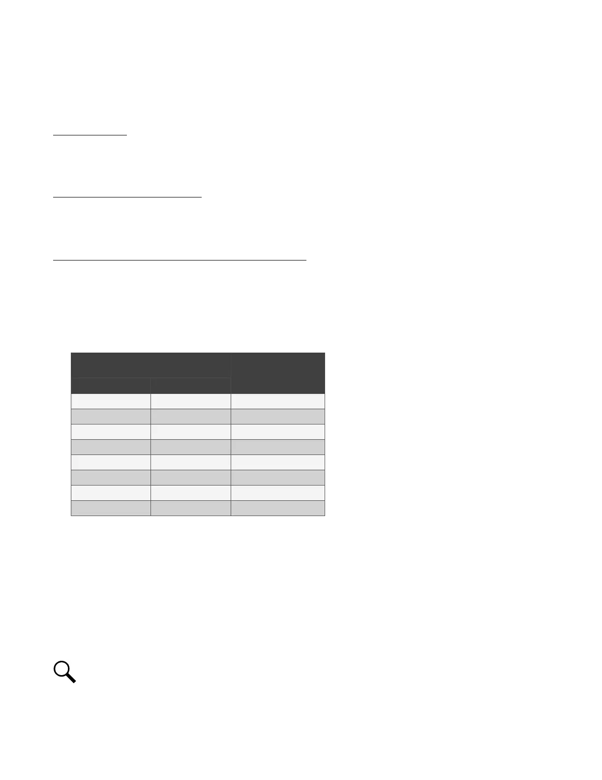
Table 5.8 CAN Port Connections
NCU CAN
Port (RJ-45)
SM-Temp Module
CAN Port
Pin Number
Pin Number Function
1 CAN L TB1-5 (CAN L)
2 CAN H TB1-3 (CAN H)
3 -- --
4 -- --
5 -- --
6 -- --
7 -- --
8 -- --
5.14 NCU Controller Ethernet Connection (if required)
The NCU Controller provides a Web Interface via an Ethernet connection to a TCP/IP network. This interface can be accessed locally
on a computer or remotely through a network. An RJ-45 10BaseT jack is provided on the front of the NCU for connection into a
customer's network. This jack has a standard Ethernet pin configuration scheme, twisted pair. Refer to Figure 5.28 and for location
and Table 5.9 for pin outs. Use shielded Ethernet cable (grounded at both ends). Note that the NCU RJ-45 jack is connected to
chassis ground. Refer to the NCU Instructions (UM1M830BNA) for operational details.
NOTE!
You can access the Web pages of the power system locally by using a "crossover" or “straight” cable connected
directly between your PC and the NCU.

 Loading...


