Vertiv™ NetSure™ 5100 Series -48 VDC Power System Installation Manual
Proprietary and Confidential © 2023 Vertiv Group Corp.
5.13.3 RS485 Modbus Connection (if required)
Refer to Figure 5.17, Figure 5.18, or Figure 5.19 for location of the RS485 Modbus connector in the system. Note the an RS485 Modbus
interface cable is available (P/N 564643). This cable is 4’ long and is terminated at one end with a mating connector and
unterminated at the other end. Refer to Table 5.2 for pinouts.
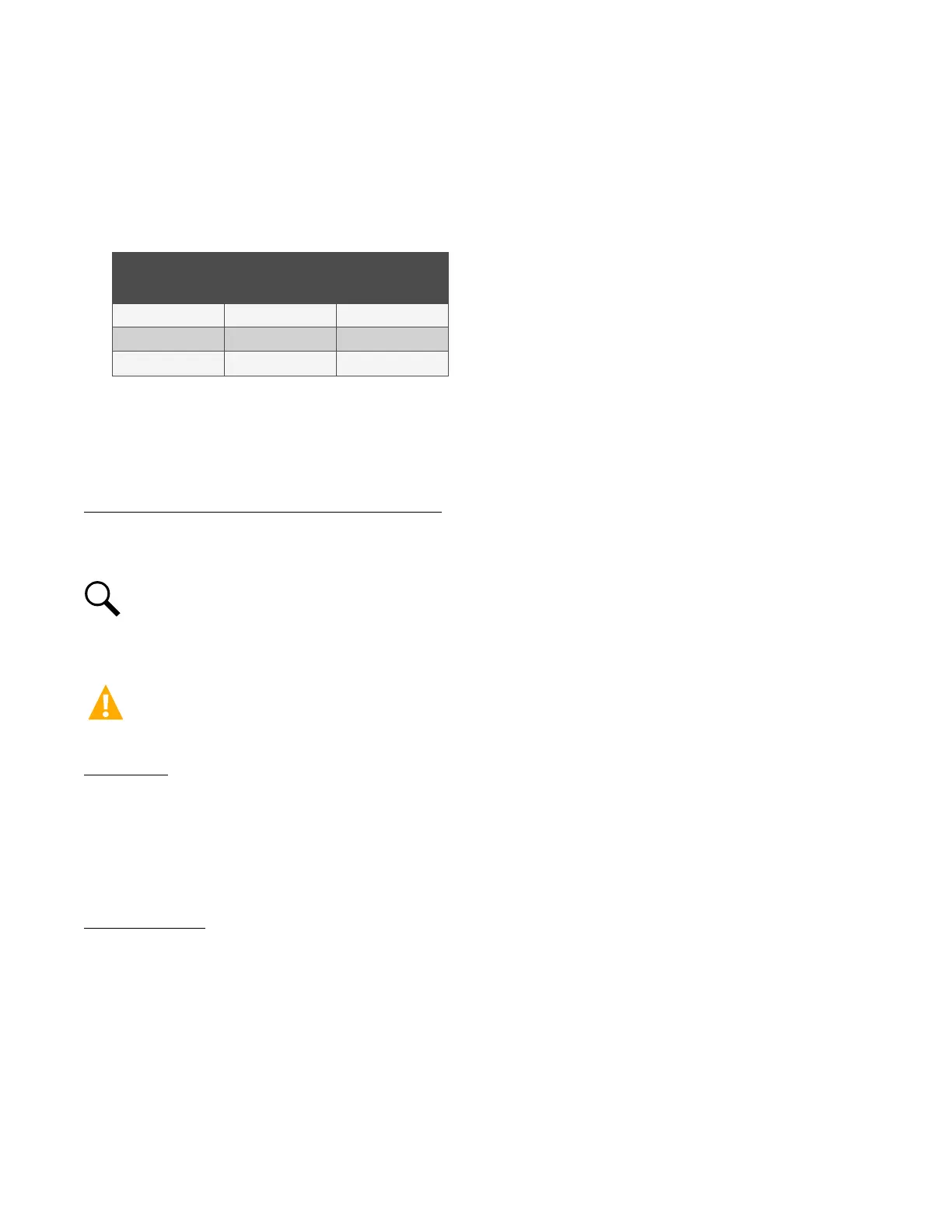
Table 5.2 RS485 Modbus Connector
RS485 Modbus Interface Cable P/N 564643
Pin Wire Color Designation
1 Red RS485A
2 Black RS485B
3 Green CGND
5.13.4 IB2 (Controller Interface Board) Connections (if required)
The IB2 (Controller Interface Board) provides connection points for digital inputs, programmable relay outputs, and temperature
probes. The IB2 interface board is mounted inside the distribution cabinet. Refer to Figure 5.17, Figure 5.18, or Figure 5.19.
Digital Inputs and Programmable Relay Outputs
Digital input and relay output leads are connected to screw-type terminal blocks located on the IB2. Recommended torque for these
connections is 2.2 in-lbs. Refer to Figure 5.21 for terminal locations. Refer to Table 5.3 and Table 5.4 for pin-out information.
NOTE!
Two sets of alarm cables are available (see SAG582137100 for part numbers). One set for the digital inputs and
another set for the relay outputs. Refer to Table 5.3 and Table 5.4 for color scheme. If the Relay Outputs Alarm Cable or
Digital Inputs Alarm Cable is ordered, one half is factory connected in the distribution cabinet. The other half has a mating
connector on one end and is un-terminated on the other end.
CAUTION! All conductors in this harness may be connected within the cabinet. Shorting or grounding of unused conductors
may result in service interruption or equipment damage. Therefore insulate all conductor ends not being used in your
application.
Digital Inputs
Connect up to seven (7) digital inputs to the IB2. Note that you must supply both paths for the digital input (either a positive or
negative signal and the opposite polarity return path). Observe proper polarity. Refer to Figure 5.21 for terminal locations and
Table 5.3 for pin-out information.
The digital inputs can be programmed to provide an alarm when the signal is applied (HIGH) or removed (LOW). Refer to the NCU
Instructions (UM1M830BNA) for programming information.
Digital Input Ratings: Refer to the following.
a) Maximum Voltage Rating: 60V DC.
b) Active High: > 19V DC.
c) Active Low: < 1V DC.
The digital inputs may be preprogrammed for specific functions. Refer to the configuration drawing (C-drawing) supplied with your
system for your system’s specific configuration.

 Loading...


