Vertiv™ NetSure™ 5100 Series -48 VDC Power System Installation Manual
Proprietary and Confidential © 2023 Vertiv Group Corp.
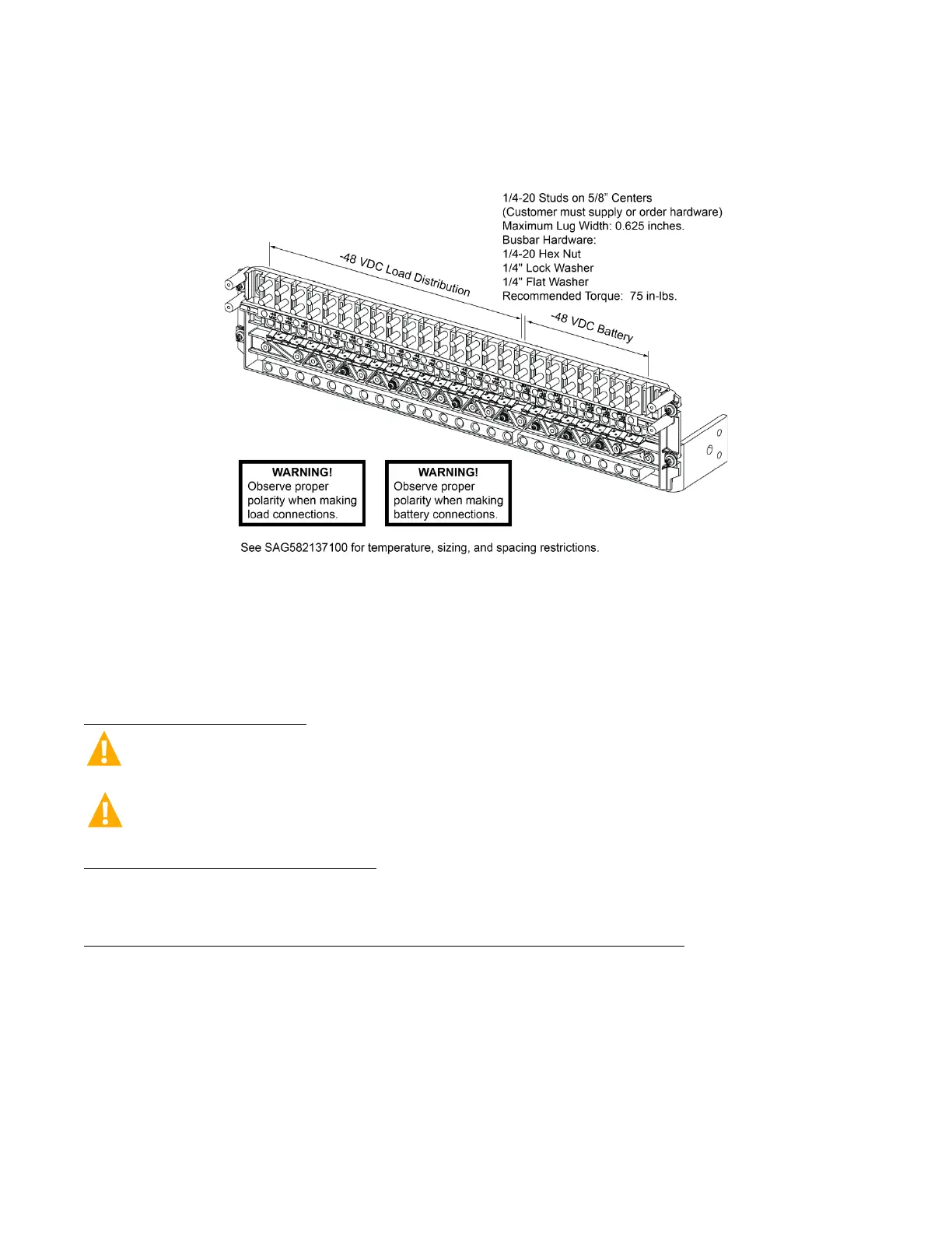
Figure 5.70 List BC Battery Connections in a List 25 Distribution Cabinet
(16) -48 VDC Load Bullet/TPS/TLS Circuit Breaker/Fuse Positions and
(8) -48 VDC Battery Disconnect Bullet/TPS/TLS Circuit Breaker/Fuse Positions
5.19.2 Input Battery Connections to List 21, 26 Distribution Cabinet
Refer to the following.
Important Safety Instructions
DANGER! Adhere to the “Important Safety Instructions” starting on page vii.
WARNING! Observe proper polarity when making output connections.
To Battery and Battery Return Busbars
Input battery leads are connected to the battery (load side) busbar and battery return busbar. Refer to Figure 5.71 for connection
details and recommended torque.
To Battery Disconnect Circuit Breakers and Battery Return Busbar (if furnished)
Input battery leads are connected to the battery disconnect device battery busbars located on the distribution panel. Battery return
leads are connected to the battery return busbar located at the top of the distribution cabinet. Refer to Figure 5.72 for connection
details. Refer to Figure 5.73 through Figure 5.75 for illustrations of the available distribution panels. Torque connections as shown in
the illustrations.

 Loading...


