Vertiv™ NetSure™ 5100 Series -48 VDC Power System Installation Manual
Proprietary and Confidential © 2023 Vertiv Group Corp.
5.4 Power System Shelf Frame Grounding Requirements
For power system shelf frame grounding requirements, refer to the current edition of the American National Standards Institute
(ANSI) approved National Fire Protection Association’s (NFPA) National Electrical Code (NEC), applicable local codes, and your
specific site requirements.
The frame grounding connection to the power system shelf is made by using grounding washers with the mounting hardware used to
secure the shelf to the relay rack or equipment cabinet. Refer to “Mounting the System in a Relay Rack or an Equipment Rack” on
page 10. Ensure that the relay rack or equipment cabinet is properly grounded.
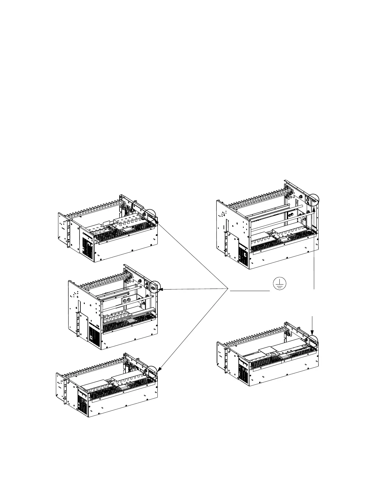
One set of frame grounding studs are also provided on the rear of the power system shelf. This provides for the installation of a lead
with a two-hole lug that has 1/4” bolt clearance holes on 5/8” centers. Connect a frame grounding lead to the studs as required. Refer
to Figure 5.2 for location and recommended torque for this connection.
Recommended frame ground wire size is 6 AWG.
Figure 5.2 Power System Shelf Frame Ground Connection
Frame Ground
Two 1/4-20 Studs and Hardware
on 5/8-inch centers.
R
ecommended Torque: 84 in-lbs.
Rear
Rear
Rear
Rear
Rear
List 21
List 20
List 25
List 26
List 27

 Loading...


