Vertiv™ NetSure™ 5100 Series -48 VDC Power System Installation Manual
Proprietary and Confidential © 2023 Vertiv Group Corp.
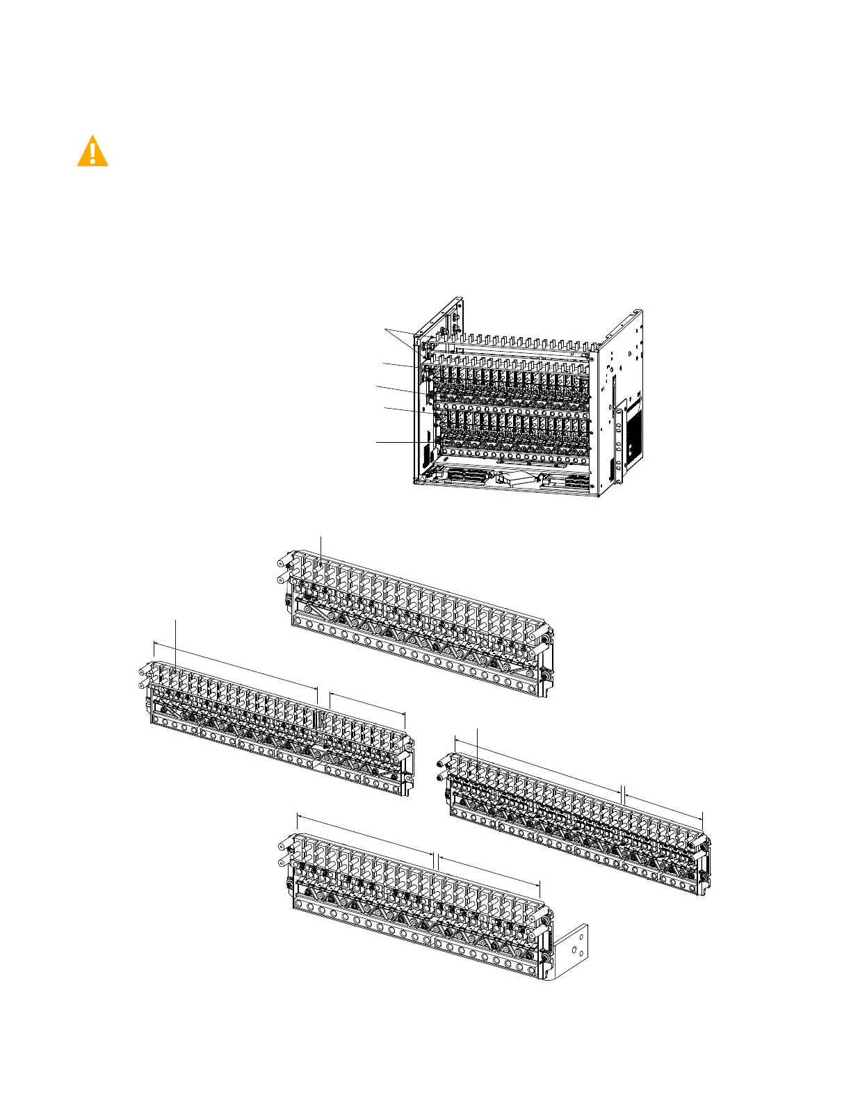
5.17.2 Load Connections to a List 21, 26 Distribution Cabinet
WARNING! Observe proper polarity when making output connections.
Load leads are connected to the individual load busbars located on the distribution panels (refer to Figure 5.41). Load return leads are
connected to separate return busbars located at the top of the distribution cabinet (refer to Figure 5.42). Refer to Figure 5.43 through
Figure 5.59 for illustrations of the available distribution panels. Torque connections as shown in the illustrations.
Figure 5.41 Load Side Connections in a List 21, 26 Distribution Cabinet
Bottom Distribution Row
Top Distribution Row
Load Return Bus
(see next page)
Load Bus
Load Bus
Load Connections (-48 VDC)
-48 VDC Load Distribution
-48 VDC Battery
-48 VDC Distribution
+24 VDC Distribution
Load Connections
Components removed in
illustration for clarity.
Distribution rows shown for sample only.
Other configurations available.
Front
1/4-20 Studs on 5/8” Centers
(Customer must supply or order hardware)
Maximum Lug Width: 0.625 inches.
Busbar Hardware:
1/4-20 Hex Nut
1/4" Lock Washer
1/4" Flat Washer
Recommended Torque: 75 in-lbs.
Load return busbars can
be rotated 90 degrees
(to route wiring through
top of cabinet).
-48 VDC Distribution
-58 VDC Distribution
Load Connections

 Loading...


