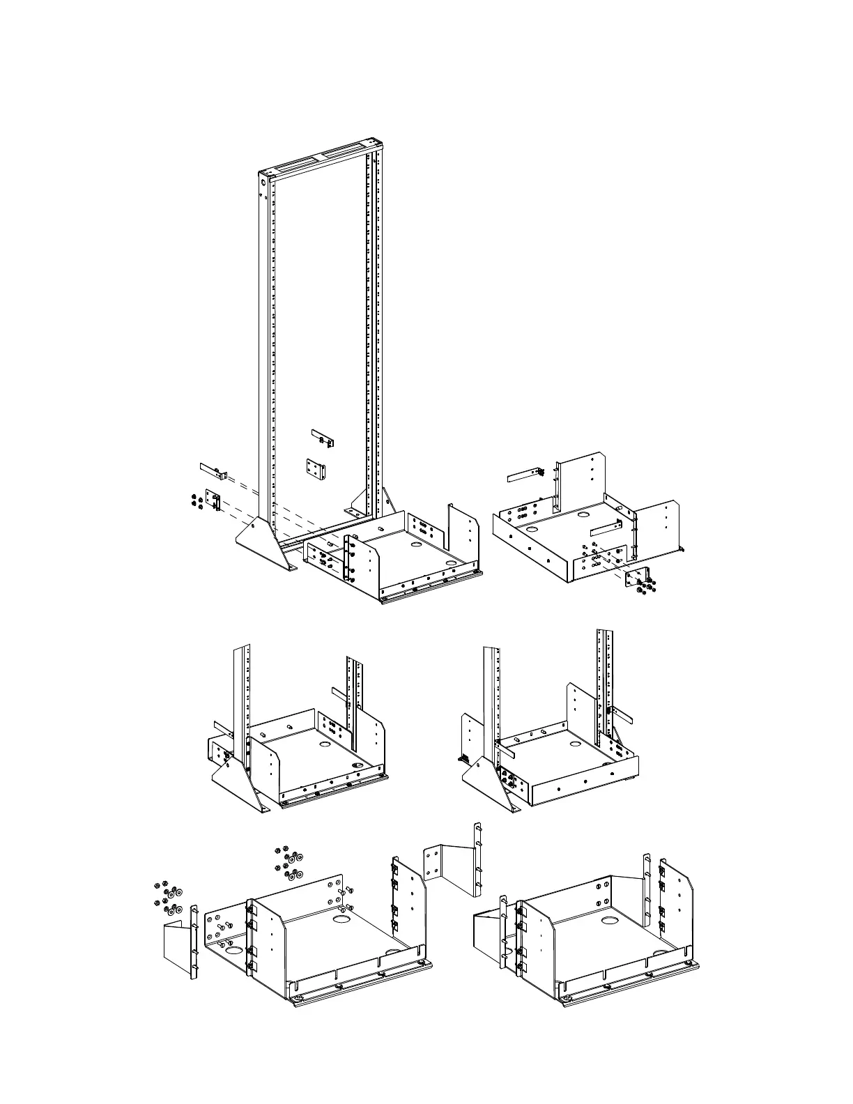
Battery
Tray
Rear
Angle
Bracket
Rear Angle Bracket
Cabling
Bracket
Front Rear
1. Slide battery tray into relay rack and
secure to relay rack with 12-24 x 3/4"
thread forming hex head screws and
#10/12 ground washers (1 place per
side) or #12 flat washers (3 places per
side). (Torque to 70 in-lbs).
2. Secure rear angle brackets (both sides)
to battery tray with 1/4-20 x 3/4” bolts,
1/4” flat washers, 1/4” lock washers, and
1/4” nuts. (Torque to 84 in-lbs).
3. Secure rear angle brackets (both sides)
to relay rack with 12-24 x 3/4" thread
forming hex head screws and #10/12
ground washers (1 place per bracket)
or #12 flat washers (1 place per bracket).
(Torque to 70 in-lbs).
4. Secure cabling brackets (both sides) to
relay rack with 12-24 x 1/2" thread forming
hex head screws. (Torque to 70 in-lbs).
P/N 559806, 559807, 559808, 559811, 10012262.
P/N 559809, 559810, 559812 similar
P/N 559809, 559810, 559812

 Loading...


