3-2 Videojet DataFlex 6530 Operator Manual - Rev AA
Main Parts
3.1.2 CLARiTY Controller Display and Power Supply Unit (PSU)
The controller consists of a removable touch screen display and power supply unit.
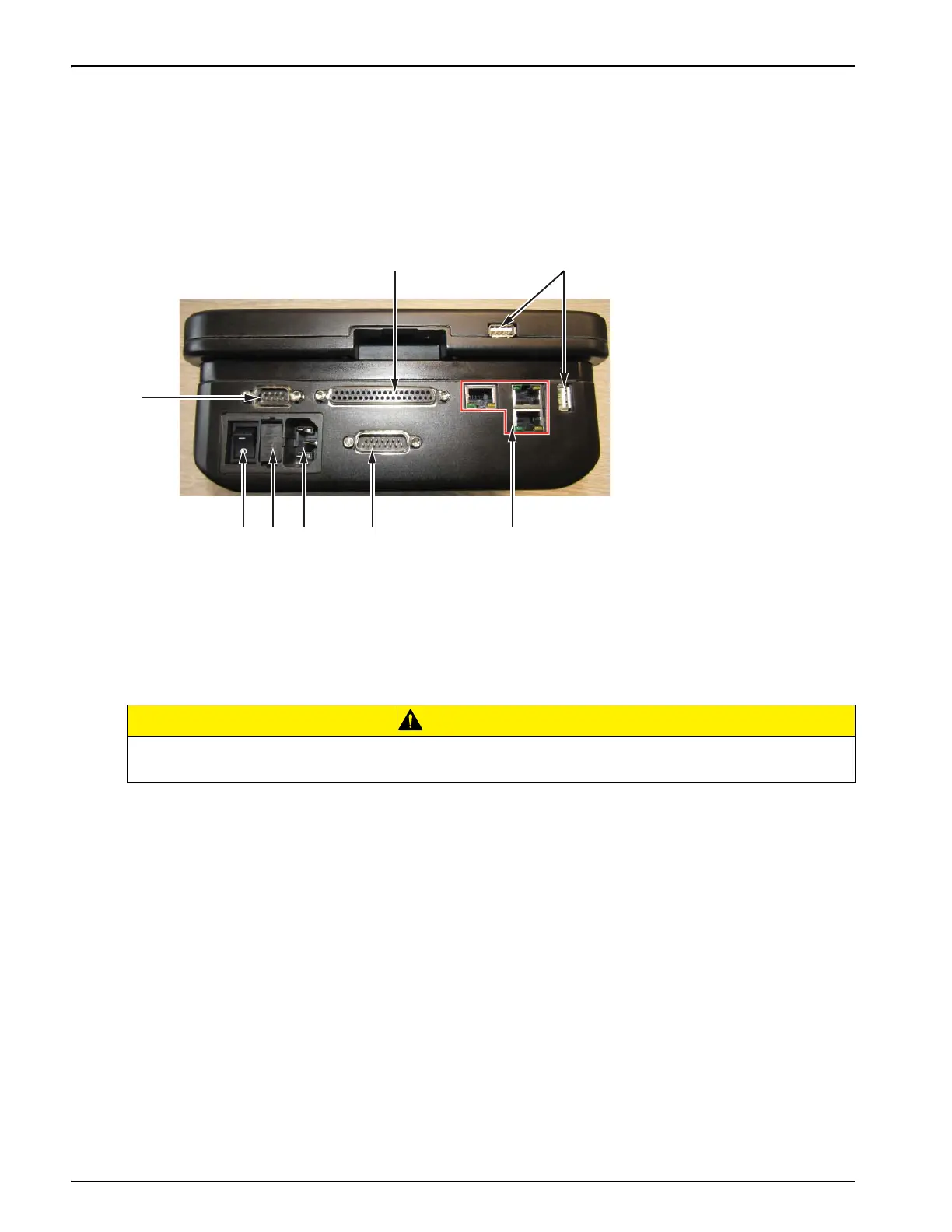
The connections to the controller is as shown in the Figure 3-7. There is an interconnecting cable
(item 1) connected from the printer to the display. Two USB ports (item 2) are provided to
upload and backup printer data and settings. The power switch (item 7) is used to turn on or off
the power supply to the CLARiTY Controller Display.
CAUTION
EQUIPMENT DAMAGE.
Ensure that the interconnecting cables are fitted correctly before power on.
Figure 3-2: Display Connections
1. Interconnecting Cable
2. USB Port (x2)
3. Ethernet Port (x3)
4. 15 Pin I/O
5. Mains Power Supply
6. Fuse 5 Amp (x2)
7. Power Switch
8. RS232