ADVANCED OPERATIONS INSTRUCTIONS FOR BUILDING A GPI TRIGGER
153
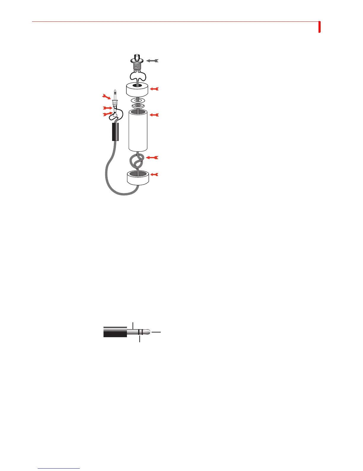
Parts Required
A “normally open momentary push-button switch”
(A).
One four-inch piece of 3/4-inch PVC pipe (C) and two
end caps (B and E).
3-conductor, 22-24 gauge stranded wire cable (D).
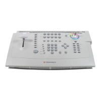
A stereo 3.5-mm mini-pin plug (F)
Instructions 1 Drill a 1/4-inch hole in the center of one PVC end cap (E) and a hole to match the
push-button switch in the other end cap (B).
2 Feed one end of the cable through the end cap with the 1/4-inch hole (E) and strip
the end of each wire.
3 Tie a single knot (D) about 8 inches from the end of the wire.
4 Slide the wire through the PVC pipe, the nut and washer, and the other end cap (B).
5 Solder the two wires at the knotted end to the two poles on the switch (A).
6 Slip the switch into the end cap and secure it using the nut and washer.
7 Solder the other ends of the cable to the plug (F).
8 Connect to the tip (G) and the base (H) of the plug. Don’t connect anything to the
middle section of the plug.
9 Push the end caps in place.
10 After you’ve tested the unit, you can cement the end caps (A and E) into place, if you
want.
11 Solder the wires of the other end of the cord to the poles from the tip and base of the
stereo mini-pin plug (F). If you aren’t sure which poles are which, ask at the store
when you make the purchase.
12 Plug your new remote trigger plug into the GPI jack on the MXProDV rear panel.
F
A
C
D
G
H
B
E