30
VERSION 03/2020 ORDER NUMBER DOC2330732
VU 1/VU 2/VU 3
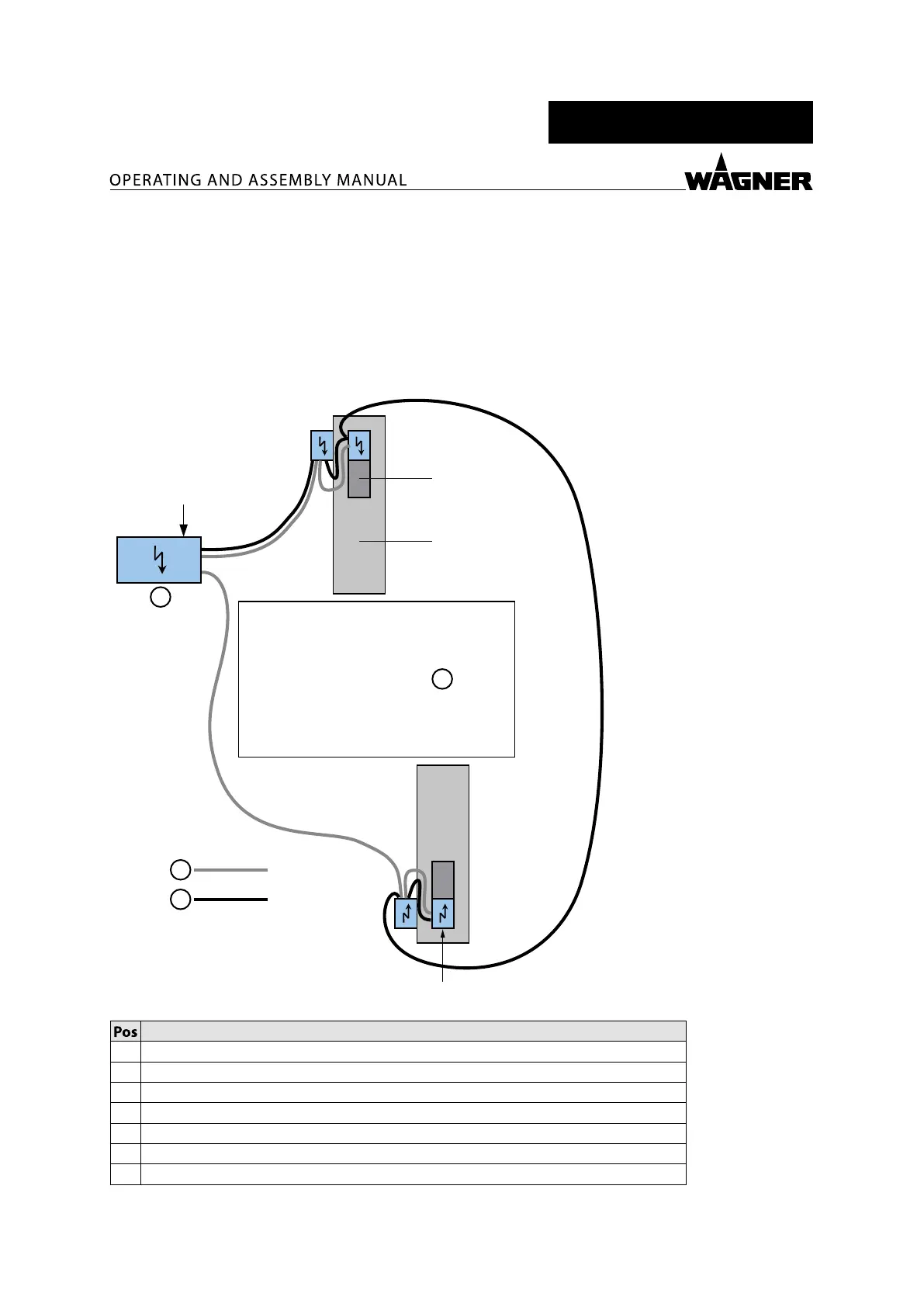
6.6.2 CONNECTING 2 RECIPROCATORS
The CAN bus topology is such that the line network has a connection on both ends.
The CAN bus connection is routed from the control cabinet, via the reciprocators and
sliding tables, all the way to the last reciprocator or sliding table, where the CAN connection
terminates.
One reciprocator is connected to each of the two voltage outputs to distribute the current load
(see gure).
P_04275
1
2
3
4
5
6
7
Designation
1 CAN bus termination
2 Reciprocator
3 Sliding table
4 Booth
5 Voltage supply
6 CAN bus
7 Control cabinet