5-100 Maintenance Procedures
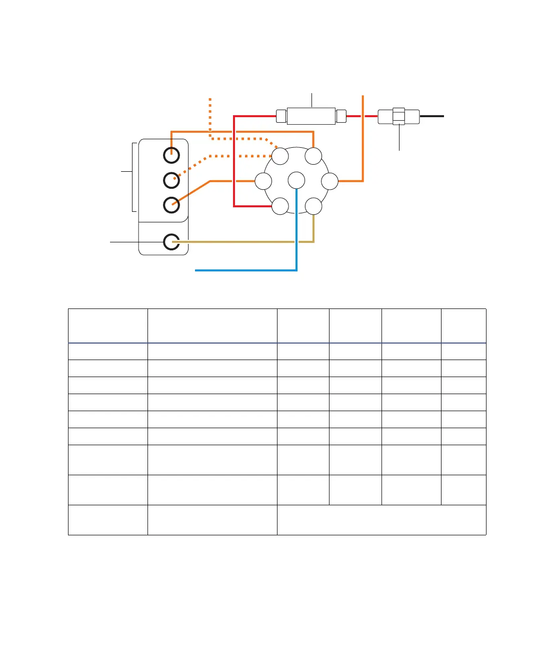
Tubing schematic — LockSpray system
Tubing dimensions – LockSpray system
Port number Connection ID (in.) OD (in.) Color
Length
(mm)
1 Vial A 0.020 1/16 Orange 680
2 Vial B 0.020 1/16 Orange 680
3 Vial C 0.020 1/16 Orange 680
4 Flow sensor 0.005 1/32 Red 200
5 Waste reservoir 0.040 1/16 Natural 1000
6 Wash reservoir 0.020 1/16 Orange 1000
7LockSpray selector
pump
0.010 1/16 Blue 300
-Flow sensor to
grounded union
0.005 1/32 Red 60
- Grounded union to
reference probe
Probe and flow-rate dependent.
A
B
C
3
1
6
5
7
4
2
From pump
From wash bottle
To
reference
probe
Waste
port
From external
reference bottle
(optional)
Flow sensor
Grounded union
Tubing
guides
Lock-spray selector valve