Description of the vehicle
5.3 Operating elements at the operator station
48
Operator’s Manual | 4080T Basic Line | 1000408123 | 05/2019 | [en]
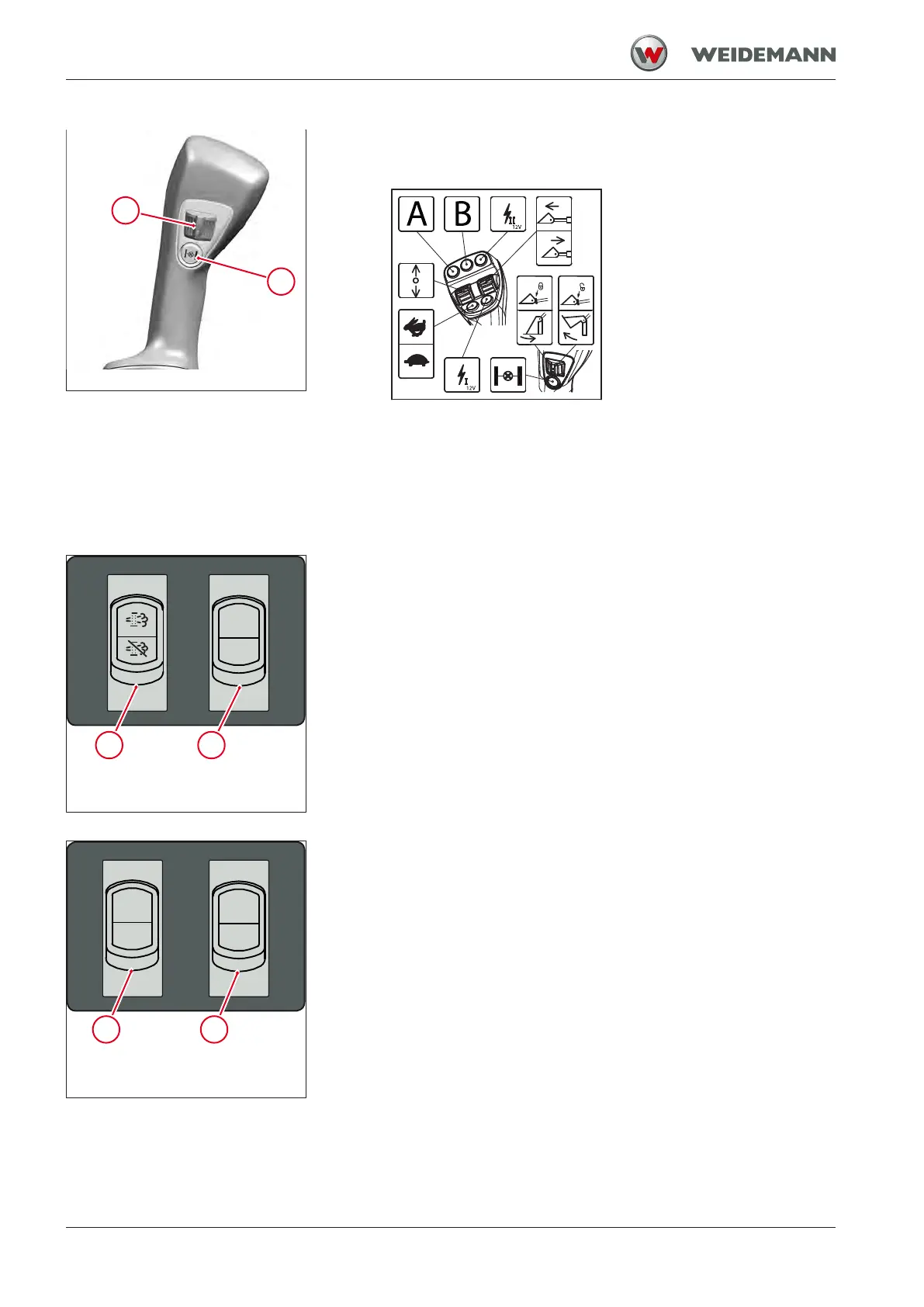
Fig.8: Switch on joystick bottom
1 Switch for the operation of the third control circuit
2 Switch for the operation of the differential lock
The label shows the assignment of the joystick. The assignment of the
joystick varies depending on the equipment of the vehicle. The label for
the joystick also changes according to the equipment.
5.3.4
Overview: Rocker switch panel
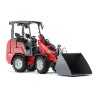
Fig.9: Switch panel 1 on instrument
panel
1 Switch for exhaust gas aftertreatment
2 Switch spare for option
Fig.10: Switch panel 2 on instrument
panel
1 Switch spare for option
2 Switch spare for option