Description of the vehicle
Operating elements at the operator station 5.3
49
[en] | 05/2019 | 1000408123 | 4080T Basic Line | Operator’s Manual
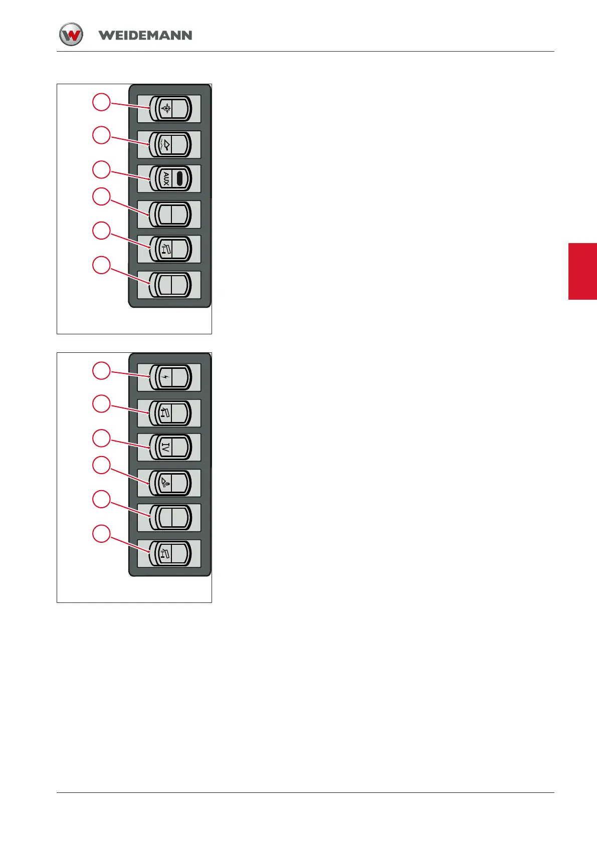
Fig.11: Switch panel 3 in the side
console
1 Switch for pressure relief of the hydraulic connections
2 Switch for floating position and load stabilizer
3 Switch for continuous operation of the third control circuit
4 Switch spare for option
5 Switch for continuous operation of rear hydraulic connections
6 Switch spare for option
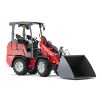
Fig.12: Switch panel 4 in the side
console
1 Rear electrical connection switch
2 Switch for rear hydraulic connections
3 Switch for changeover third/fourth control circuit
4 Switch for locking the loader unit
5 Switch spare for option
6 Switch for changing rear hydraulic connections
5