CYLINDER
BLOCK
SERVICE
9. Install the oil seal into the crankshaft rear oil seal case.
Install the seal case to the cylinder block. Remember to
install the
gasket. Turn the crankshaft one complete revo-
lution
to
ensure there is
no
unwanted binding.
10. Install the back plate.
11. Install the flywheel. The bolts should be tightened to the
specified torque.
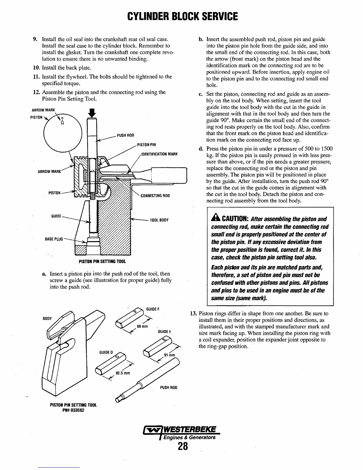
12. Assemble the piston and the connecting rod using the
Piston Pin Setting Tool.
CONNECTING
ROO
/////';I'E'-
__
TOOL
BOOY
PISTON
PIN
SETTING
TOOL
3.
Insert a piston pin into the push rod
of
the tool, then
screw a guide (see illustration for proper guide) fully
into the push rod.
/1);0"
~9~m
~
GUIDEE
G~;>
~.~m
~
~~
~
PISTON
PIN
SETTING
TOOL
PN#033582
PUSH
ROD
h. Insert the assembled push rod, piston pin and guide
into the piston pin hole from the guide side, and into
the small end
of
the connecting rod.
In
this case, both
the arrow (front mark) on the piston head and the
identification mark on the connecting rod are
to
be
positioned upward. Before insertion, apply engine oil
to
the piston pin and to the connecting rod small end
hole.
c.
Set the piston, connecting rod and guide as an assem-
bly on the tool body. When setting, insert the tool
guide into the tool body with the cut
in
the guide
in
alignment with that
in
the tool body and then turn the
guide
90°. Make certain the small end
of
the connect-
ing rod rests properly on the tool body. Also, confirm
that the front mark on the piston head and identifica-
tion mark on the connecting rod face up.
d.
Press the piston pin
in
under a pressure
of
500 to 1500
kg. If the piston pin is easily pressed
in
with less pres-
sure than above,
or
if the pin needs a greater pressure,
replace the connecting rod or the piston and pin
assembly. The piston pin will be positioned
in
place
by the guide. After installation, tum the push rod
90°
so that the cut in the guide comes in alignment with
the cut in the tool body. Detach the piston and con-
necting rod assembly from the tool body.
A
CAUTION:
After
assembling
the
piston
and
connecting
rod,
make
certain
the
connecting
rod
small
end
is
properly
positioned
at
the
center
01
the
piston
pin.
II
any
excessive
deviation
Irom
the
proper
position
is
lound!l
correct
it.
In
this
case,
check
the
piston
pin
setting
tool
also.
Each
pislon
and
its
pin
are
matched
parts
and!l
therefore,
a set
01
piston
and
pin
must
not
be
confused
with
other
pistons
and
pins.
All
pistons
and
pins
to
be
used
in
an
engine
must
be
of
.the
same
size
(same
mark).
13. Piston rings differ in shape from one another. Be sure to
install them
in
their proper positions and directions, as
illustrated, and with the stamped manufacturer mark and
size mark facing up. When installing the piston ring with
a coil expander, position the expander joint opposite
to
'the ring-gap position.
Engines & Generators
28
 Loading...


