PROCEDURE
1 Attach the O-rings to the applicable HP fuel pipes (002 and 007, Figure 13-15).
2 Remove all of the protection from the sealing faces.
3 Make sure that the claws (001, 004, 006, 010) are correctly attached to the HP fuel
pipes (002, 007).
NOTE: You can adjust the claws with an open-ended wrench.
4 Make sure that the distance X between the ends of the HP fuel pipes (002, 007) and
their related claws (001, 004, 006, 010) refers to Table 13-4 - Distance X for HP fuel
pipe.
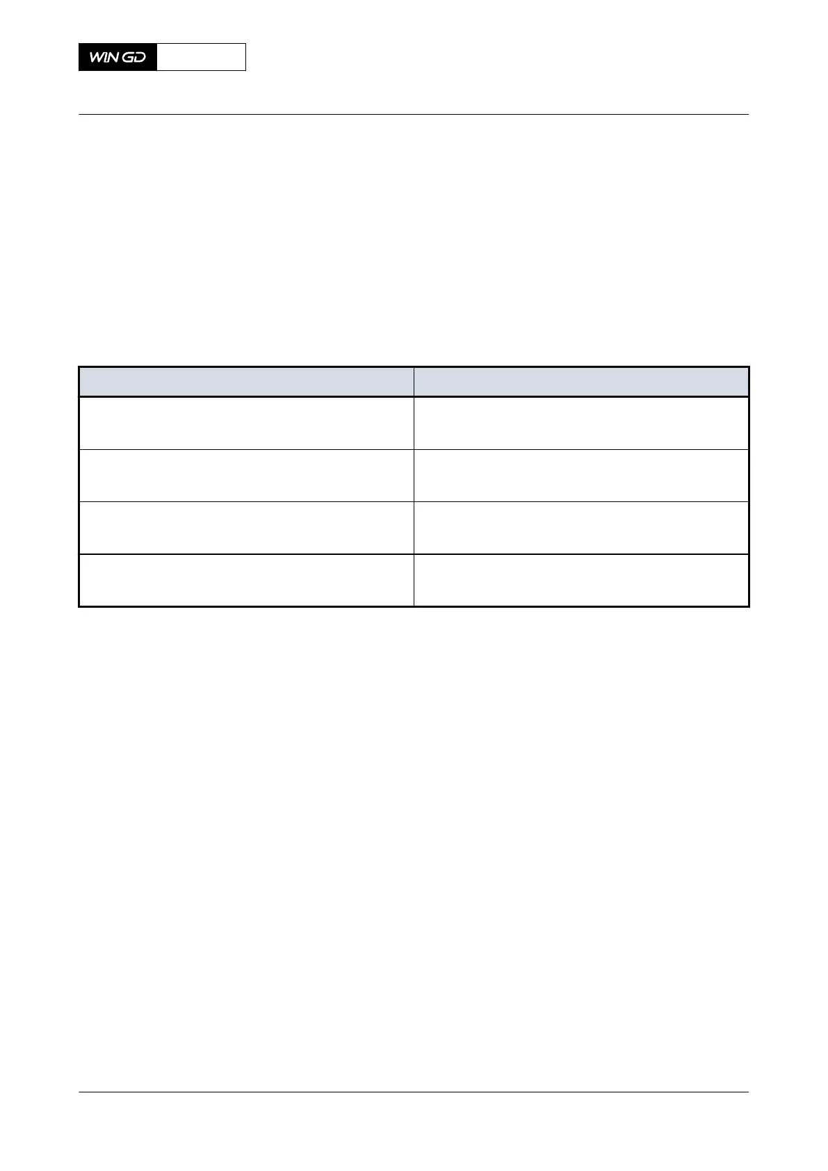
Tab 13-4 Distance X for HP fuel pipe
Engine type Distance X [mm]
X52
X52DF
xxx
X62 / -B
X62DF
xxx
X72 / -B
X72DF
14.0
X92 / -B
X92DF
14.0
X72DF
AA00-8752-00AAA-720A-A
Maintenance Manual HP fuel pipe (fuel pump to fuel rail) - install
Winterthur Gas & Diesel Ltd.
- 765 - Issue 002 2020-10