PROCEDURE
1 Release the pressure of the test bench.
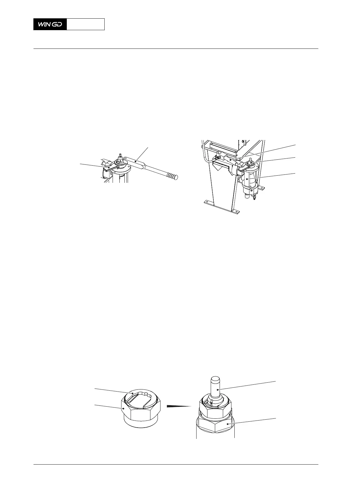
2 Remove the safety container from the valve holder (003, Figure 7-43).
3 Disconnect the HP hose from the connecting piece.
4 Disconnect the cable from the test bench.
Fig 7-43 Direct controlled injection valve - disassemble
5 Turn the valve holder (003) through 180° so that the nozzle tip (002) points up.
6 Safety the valve holder (003) in that position on the test bench.
7 Loosen the locknut of the nozzle tip (002).
8 If it is necessary to remove the nozzle tip (002) from the nozzle body, do as follows:
8.1 Remove the loosened locknut.
8.2 Make sure that the needle, the compression spring and the tappet are removed
from the coupling nut (002, Figure 7-44).
NOTE: It is possible, but not recommended, to replace the nozzle tip with the
needle installed. Remove only the locknut.
8.3 Attach the hexagonal nut (003) to the coupling nut (002).
8.4 Put the plate (004) in the clearance between the coupling nut (002) and the
nozzle tip (001).
8.5 Carefully turn the hexagonal nut (003) up to move the nozzle tip (001).
8.6 Remove the nozzle tip (001) from the coupling nut (002).
8.7 Remove the plate (004) and the hexagonal nut (003) from the nozzle tip (001).
Fig 7-44 Nozzle tip - remove
X72DF
AA00-2722-00AAA-530A-A
Maintenance Manual Direct controlled injection valve - disassemble
Winterthur Gas & Diesel Ltd.
- 265 - Issue 002 2020-10