PROCEDURE
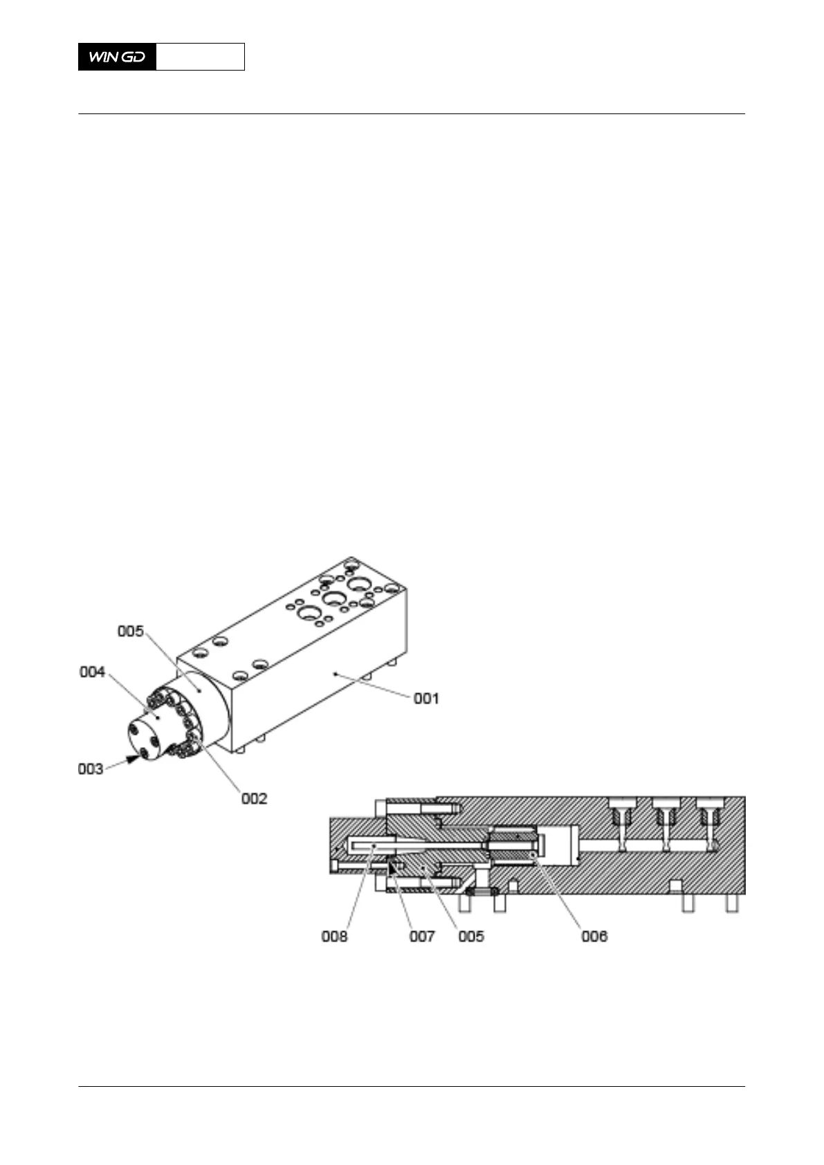
1 If it is necessary to assemble the flange (005, Figure 10-32) and the piston rod (008), do
as follows:
NOTE: If possible do this step with the FLV in vertical position.
1.1 Clean the sealing surfaces of the flange (005) and of the valve block (001).
1.2 Put the flange (005) together with the piston rod (008) and the piston (006) in
position on the valve block (001).
NOTE: Always use the flange (005) and the related piston rod (008) as a pair.
1.3 Apply Never Seez NSBT to the threads of the Allen screws (002).
1.4 Tighten symmetrically with your hand the Allen screws (002).
1.5 Torque symmetrically the Allen screws (002) in two steps to 60 Nm.
1.6 Make sure that the piston rod (008) moves freely.
1.7 Put oil on the new O-ring (007).
1.8 Attach the new O-ring to the cover (004).
1.9 Attach the cover (004) to the flange (005) with the Allen screws (003).
1.10 Tighten the Allen screws (003).
Fig 10-32 Flow limiting valve - install the flange
2 Make sure that the dowel pins are in the fuel rail.
X72DF
AA00-5565-00AAA-720A-A
Maintenance Manual Flow limiting valve - install
Winterthur Gas & Diesel Ltd.
- 609 - Issue 002 2020-10