3 Turn over the valve block (001, Figure 10-33).
4 Clean the sealing surface in the valve block (001).
5 Put the new lip seal (003) into the valve block (001).
6 Turn over the valve block (001).
7 Clean the seating areas on the valve block (001) and on the fuel rail.
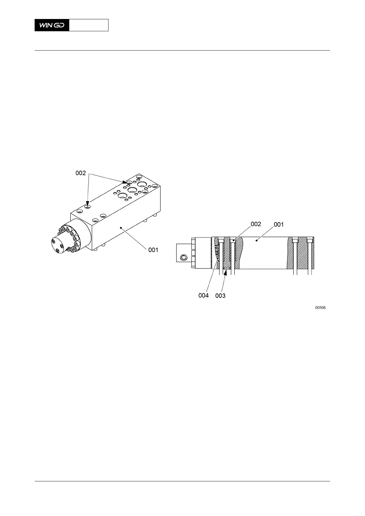
Fig 10-33 Flow limiting valve - install
8 Apply Never Seez NSBT to the threads and surfaces that touch on the Allen screws
(002).
9 Make sure that the distance sleeves (004) are in the positions shown.
10 Attach the valve block (001) to the fuel rail with the Allen screws (002).
11 Torque symmetrically the Allen screws (002) to the correct value, refer to section 16.1
Tightening instructions.
12 If possible, put an applicable device through the hole of the return pipe connection and
make sure that the position of the piston rod (008, Figure 10-33) is correct.
X72DF
AA00-5565-00AAA-720A-A
Maintenance Manual Flow limiting valve - install
Winterthur Gas & Diesel Ltd.
- 610 - Issue 002 2020-10