EasyManua.ls Logo

Wolf BWL-1S-07 User Manual

Wolf BWL-1S-07
120 pages
To Next Page IconTo Next Page
Page #1 background imageLoading...
Page #1 background image
Installation and operating instructions
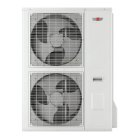
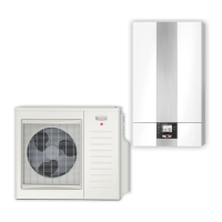
Split air/water heat pump
BWL-1S -05/230 V BWL-1S -10/400 V
BWL-1SB -05/230 V BWL-1SB-10/400 V
BWL-1S -07/230 V BWL-1S -14/400 V
BWL-1SB -07/230 V BWL-1SB-14/400 V
BWL-1SB -10/230 V BWL-1S -16/400 V
BWL-1SB -14/230 V BWL-1SB-16/400 V
GB
WOLF GMBH / P.O. BOX 1380 / D-84048 MAINBURG / TEL. +49(0) 87 51 74- 0 / FAX +49(0) 87 51 74- 16 00 / www.wolf.eu
Doc. no.: 3064298_201805 Subjecttomodications
Integrated system log book
From:
2016 appliance version
HCM-3 FW 1.70
AM FW 1.60
BM-2 FW 2.30
Table of Contents

Other manuals for Wolf BWL-1S-07

Questions and Answers:

Wolf BWL-1S-07 Specifications

General IconGeneral
BrandWolf
ModelBWL-1S-07
CategoryHeat Pump
LanguageEnglish

Summary

Safety Instructions, Standards, and Regulations

Safety Information

Highlights personal and operational safety information using symbols and warnings.

Regulations and Directives for Installation, Commissioning, Maintenance, and Repair

Specifies regulations and directives to be observed during all phases of appliance.

Information on the Heat Pump

Operating Principle of a Heat Pump

Explains the thermodynamic cycle of the heat pump.

Structure

BWL-1S(B) Indoor Module

Details the components and layout of the indoor module.

Equipment Features

BWL-1S(B) Dimensions

Indoor Module

Provides dimensional drawings and measurements for the indoor module.

Siting the BWL-1S(B)

Siting Instructions

Provides guidelines for selecting an appropriate installation site for the heat pump.

Siting the Outdoor Module

Minimum Clearances for the Outdoor Module

Illustrates required clearances around the outdoor unit for air circulation.

Siting the Indoor Module

Minimum Clearances for the Indoor Module

Shows required clearances around the indoor unit.

Securing the Appliance with the Suspension Bracket

Provides instructions for securely mounting the indoor module.

Gravel Bed and Foundation Diagram

Anchorage and Anti-vibration Mounts

Concrete Foundation

Details the installation of the unit on a concrete foundation.

Wall Mounting

Details the installation of the unit using wall mounting brackets.

Connecting the Refrigerant Lines

Connecting the Refrigerant Line to the Outdoor Module

Provides instructions for connecting refrigerant lines to the outdoor unit.

Connecting the Refrigerant Line to the Indoor Module

Provides instructions for connecting refrigerant lines to the indoor unit.

Leak and Pressure Testing

Details the procedure for leak and pressure testing the refrigerant circuit.

Filling the Refrigerant Lines

Filling the Indoor Module and Refrigerant Lines

Describes the process of filling the refrigerant lines.

Checking the Refrigerant Circuit for Leaks

Explains how to check the refrigerant circuit for leaks.

Connecting the Heating/DHW Circuit

Observe the Following Points for the Heating/DHW Circuit

Lists important points to consider for the heating/DHW circuit connections.

Filling the Heating System

Describes the process of filling and venting the heating system.

CHC Split / 200 Heat Pump Centre

CHC Split / 300 Heat Pump Centre

Dimensions / Minimum Clearances

Provides dimensional data and minimum clearance requirements.

Electrical Connection

Mains Feed / Connection

Details mains power supply connections for indoor and outdoor modules.

Outdoor Module Electrical Connection

BWL-1S(B)-05/07 Outdoor Module Electrical Connection

Wiring diagram and connection details for the outdoor module.

BWL-1S(B)-10/14/16 Outdoor Module Electrical Connection

Wiring diagrams for 400V and 230V outdoor modules.

Indoor Module Electrical Connection

Opening / Unhooking the Indoor Module Casing

Instructions for accessing the indoor module's internal components.

Electric Heater Connection

Details on connecting the electric heater and its configurations.

PSU / PV / Smart Grid / ODU Bus Connection

Explains connections for power supply, PV, Smart Grid, and ODU bus.

HCM-3 PCB Connection

Wiring diagram for the HCM-3 PCB and its terminals.

Electrical Connection (230 V)

Details for the 230 V mains connection and output Z1.

Electrical Connection (Low Voltages)

Details for low voltage connections like sensors and accessories.

Indoor Module HCM-3 PCB Wiring Diagram

Comprehensive wiring diagram for the HCM-3 PCB.

Indoor Module EWO Board / AWO Board Wiring Diagram

Wiring diagram for the EWO and AWO communication boards.

AM Display Module / BM-2 Programming Unit

Installation

Instructions for installing the AM or BM-2 unit.

Operating Mode / HP Status

Operating Mode

Lists and describes the different operating modes of the heat pump.

HP Status

Lists and describes the status indicators for the heat pump.

Contractor Level

AM Menu Structure, Contractor Level

Diagram showing the menu structure for contractor access on AM module.

BM-2 Menu Structure, Contractor Level

Diagram showing the menu structure for contractor access on BM-2 unit.

Description

Explains contractor level menus for System, Parameters, and Special functions.

Relay Test

Allows manual actuation of outputs and actuators for testing.

Parameter Reset

Explains how to reset all settings and statistical data to factory defaults.

Heating Curve

Instructions for setting the heating curve for optimal efficiency.

Cooling Curve

Instructions for setting the cooling curve for active cooling mode.

Contractor Parameters

Overview

Lists contractor parameters with their designations, settings, and factory settings.

Active Cooling Parameters

Details parameters related to active cooling functions.

Compressor Parameters

Details parameters related to compressor operation and dual modes.

Contractor Parameters Description

Provides detailed descriptions for specific contractor parameters.

System Configurations

Overview

Lists available system configurations for BWL-1S and BWL-1SB.

Additional Functions

Active Cooling

Details the conditions and requirements for active cooling mode.

Configuring the Dual Mode Point

Heating Output, Power Consumption, COP

Commissioning

Key Criteria for Commissioning

Lists essential checks to be performed before commissioning the system.

Troubleshooting

General Information

General advice on safety, fault handling, and component replacement.

Procedure in the Case of Faults

Step-by-step guide for diagnosing and resolving faults.

Fault Codes

A table listing fault codes, their causes, and remedies.

Related product manuals