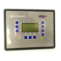
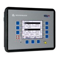
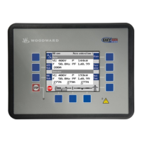
Manual 37278B GCP-30 Series - Genset Control
Page 6/174 © Woodward
Illustrations And Tables
Illustrations
Figure 3-1: Control loop ........................................................................................................................................................... 31
Figure 3-2: Step response (Example) ........................................................................................................................................ 32
Figure 3-3: Step responds - governor configuration ................................................................................................................. 34
Figure 3-4: CAN bus load/var sharing, wiring diagram ............................................................................................................ 51
Figure 3-5: CAN bus load/var sharing, diagram ....................................................................................................................... 51
Figure 3-6: Breaker control logic 'Impulse'............................................................................................................................... 75
Figure 3-7: Breaker control logic 'Continuous' ......................................................................................................................... 76
Figure 3-8: Characteristic of the time-overcurrent monitoring ................................................................................................. 96
Figure 3-11: Sprinkler operation ............................................................................................................................................. 113
Figure 3-12: VDO transmitter 323.805/001/001 (slope) ......................................................................................................... 120
Figure 3-13: Start-Stop sequence: Gas engine ........................................................................................................................ 126
Figure 3-14: Wiring diagram for opening gas valves with the GCP-30 from V4.1001 .......................................................... 127
Figure 3-15: Start-stop sequence: Diesel engine ..................................................................................................................... 129
Figure 3-16: Delayed engine monitoring ................................................................................................................................ 132
Figure 4-1: Analog outputs - cosϕ scaling .............................................................................................................................. 143
Tables
Table 1-1: Manual - Overview .................................................................................................................................................... 7
Table 1-2: Functional overview .................................................................................................................................................. 8
Table 3-1: Event recorder - Messages, part 1 ........................................................................................................................... 19
Table 3-2: Event recorder – Messages, part 2 ........................................................................................................................... 20
Table 3-3: Set point value table ................................................................................................................................................ 31
Table 3-4: Limit values, permissible limits ............................................................................................................................... 62
Table 3-5: Limit values generator, dead bus start ..................................................................................................................... 65
Table 3-6: Limit values mains, dead bus start ........................................................................................................................... 66
Table 3-7: Limit values, Emergency power .............................................................................................................................. 86
Table 3-9: Discrete alarm inputs - delay stages ...................................................................................................................... 106
Table 3-10: Function - external operation mode selection ...................................................................................................... 108

 Loading...

