appropriate
memory
stack
locations
as
specified
by
the
TSAi however, subsequent
values
of
the
Space
Count
are
indeterminate.
During a
PLS
instruction,
the
Space
Count
is
incremented
by 1 for
each
word
pulled
from
the
memory
stack.
If
the
Space
Count
is
incremented
beyond a
value
of
32,767,
bit
position
32
is
set
to 1 (signifying an overflow
condition);
however,
the
PLS
instruction
continues
(i.
e.,
no
trapping
occurs).
Note:
Once
bit
position
32
has
been
set
to a 1,
it
can
be
reset
to a 0
only
by
executing
a Mode
0,
WRITE
DIRECT
instruction.
That is,
bit
position
32
can
not
be
reset
to a 0 by
the
decrementing
process
per-
formed during a
PSS
instruction.
WORD
COUNT
The Word
Count
field
(bit positions
49-63)
of
the
Status
Stack
Pointer Doubleword is a
lS-bit
counter
that
may
con-
tain
a
value
of
0 through
32,767.
Depending upon
pro-
gramming
considerations,
the
initial
Word
Count
is a
specific
value
either
as
the
result
of
executing
a Mode
0,
WRITE
DIRECT
instruction
or
as
the
result
of
executing
a
PSS
or
PLS
instruction.
During a
PSS
instruction,
the
Word
Count
is
incremented
Ly
1
[V
1-
~uch
yvvi"d
pu~hcd
il.tv
th~
iii\:i;;Gr'j
~t~~k.
Th~~,
the
terminal Word
Count
for a
PSS
instruction
exceeds
the
initial
Word
Count
by 28.
If
the
Word
Count
value
exceeds
32,767,
bit
position
48
is
set
to a 1 (signifying
that
an overflow
condition
has
occurred);
however,
the
PSS
instruction
continues
the
stacking
operation
(i.
e.,
no
trapping occurs).
If
the
initial
Word
Count
for a
PLS
instruction
is
equal
to
or
greater
than 28,
the
Word
Count
is
decremented
by 1 for
each
word
pulled
from the memory
stack
and
the
terminal
Word
Count
will
be
28 less than
the
initial
Word
Count.
Note
that
if
bit
position
48
was set to a 1 by a
PSS
instruc-
tion
previously,
it
can not be reset
to
a 0 by
the
decrement-
ing performed during a
PLS
instruction.
If the
initial
Word
Count
for a
PLS
instruction
is
equal
to
zero,
the
parameters
within
the
Status
Stack
Pointer
Double-
word
are
neither
effective
nor
affected
by the
PLS
instruc-
tion.
However,
default
PSWs
are
loaded from
real
memory
locations
2 and
3.
If the
initial
Word
Count
for a
PLS
instruction
is less than 28
and
not
equal
to
zero,
the
other
parameters
of
the
Status
Stack
Pointer Doubleword
are
not
effective
and
none
of
the
parameters
are
affected
by
the
PLS
instruction.
Instead
the
BP
traps to
location
X
'
4D
'
(instruction
exception
trap)
and
TCC2 is set.
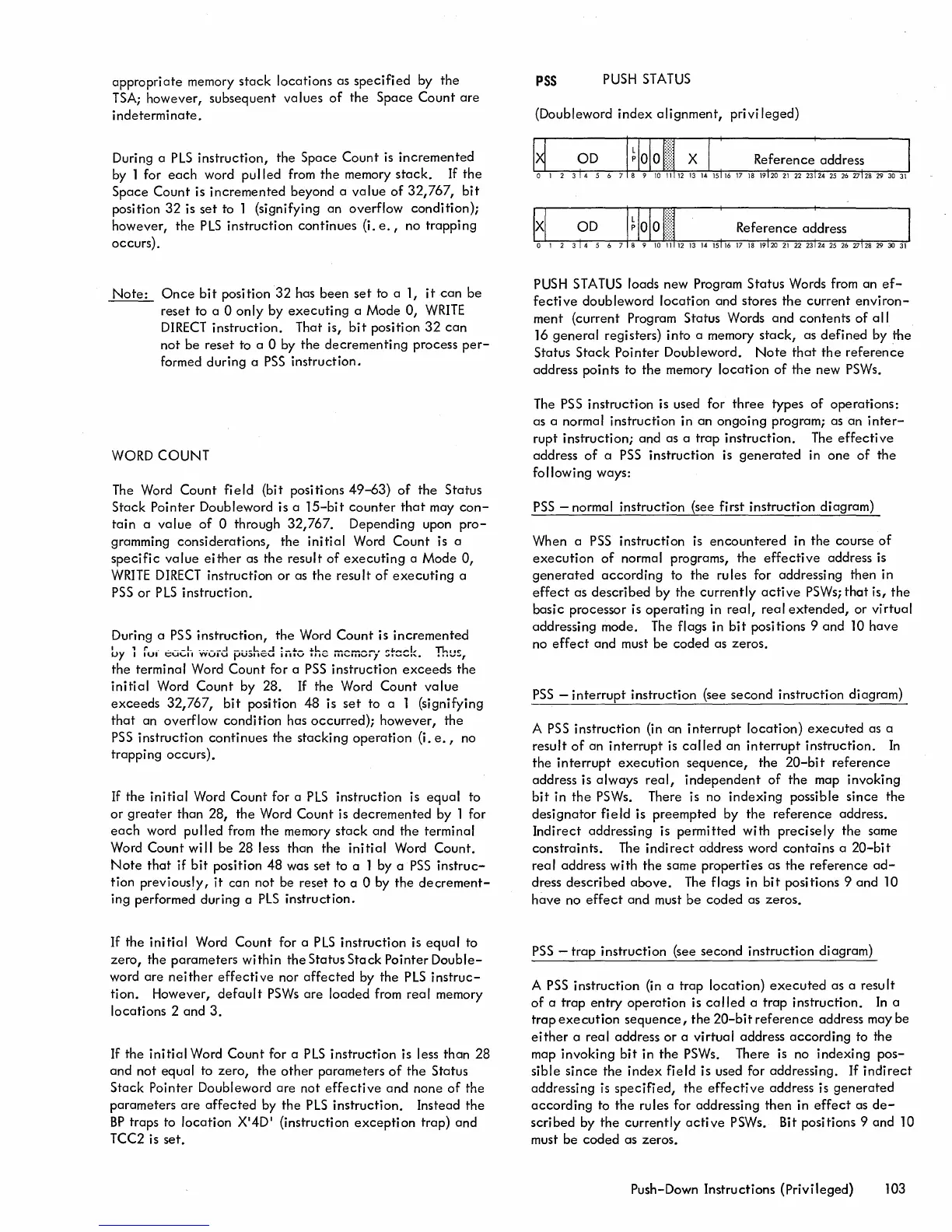
PSS
PUSH
STATUS
(Doubleword
index
alignment,
privi
leged)
!xl
aD
PUSH
STATUS
loads new Program
Status
Words from an
ef-
fective
doubleword
location
and stores
the
current
environ-
ment (current Program Status Words
and
contents
of
all
16
general
registers)
into
a memory
stack,
as
defined
by
the
Status
Stack
Pointer
Doubleword.
Note
that
the
referen~e
address points to
the
memory
location
of
the
new
PSWs.
The
PSS
instruction
is used for
three
types
of
operations:
as a normal instruction in an
ongoing
program; as
an
inter-
rupt
instruction;
and as a
trap
instruction.
The
effective
address
of
a
PSS
instruction is
generated
in
one
of
the
following ways:
PSS
- normal instruction (see first
instruction
diagram)
When a
PSS
instruction is
encountered
in
the
course
of
execution
of
normal programs,
the
effective
address is
generated
according
to the rules for addressing then in
effect
as
described
by
the
currently
active
PSWs;
that
is,
the
basic
processor is
operating
in
real,
real
extended,
or
virtual
addressing mode. The flags in
bit
positions 9 and 10
have
no
effect
and must be coded as zeros.
PSS
-
interrupt
instruction
(see
second
instruction
diagram)
A
PSS
instruction
(in an
interrupt
location)
executed
as a
result
of
an
interrupt
is
called
an
interrupt
instruction.
In
the
interrupt
execution
sequence,
the
20-bit
reference
address is
always
real,
independent
of
the
map invoking
bit
in
the
PSWs. There is no
indexing
possible
since
the
desi
gnator
fi
e
ld
is
preempted
by
the
reference
address.
Indirect
addressing is
permitted
with
precisely
the
same
constraints.
The
indirect
address word
contains
a
20-bit
real
address
with
the
same
properties
as
the
reference
ad-
dress
described
above.
The flags in
bit
positions 9 and 10
have
no
effect
and must
be
coded
as zeros.
PSS
-
trap
instruction
(see
second
instruction
diagram)
A
PSS
instruction
(in a trap
location)
executed
as a resu
It
of
a
trap
entry
operation
is
called
a
trap
instruction.
In
a
trap
execution
sequence,
the
20-bit
reference
address may be
either
a
real
address
or
a virtual address
according
to the
map
invoking
bit
in
the
PSWs. There is no
indexing
pos-
sible
since
the
index
field
is used for addressing.
If
indirect
addressing
is
specified,
the
effective
address is
generated
according
to
the
rules for addressing
then
in
effect
as
de-
scribed
by
the
currently
active
PSWs. Bit positions 9 and 10
must be
coded
as zeros.
Push-Down Instructions
(Privileged)
103

 Loading...


