ChipScope Pro Software and Cores User Guide www.xilinx.com 13
UG029 (v14.3) October 16, 2012
ChipScope Pro Cores Description
Using Multiple Trigger Ports
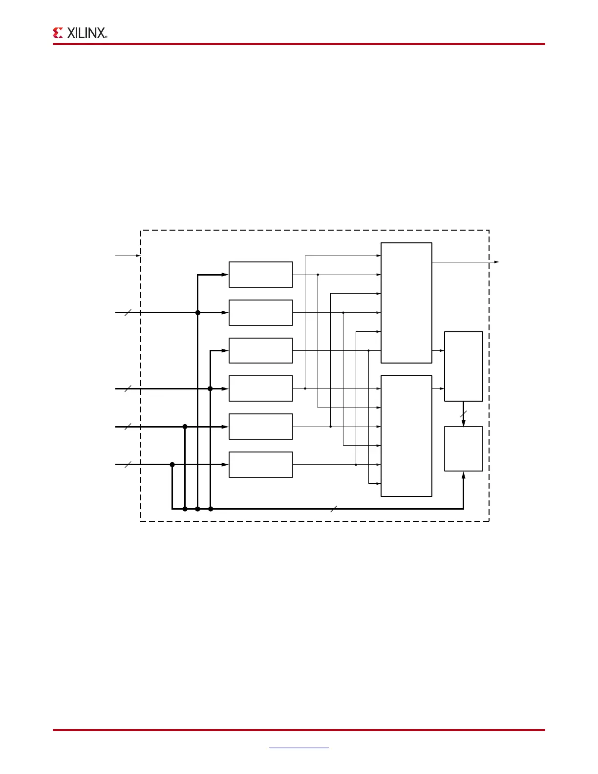
The ability to monitor different kinds of signals and buses in the design requires the use of
multiple trigger ports. For example, if you are instrumenting an internal system bus in
your design that is made up of control, address, and data signals, then you could assign a
separate trigger port to monitor each signal group (as shown in
Figure 1-3).
If you connected all these different signals and buses to a single trigger port, you would
not be able to monitor for individual bit transitions on the CE, WE, and OE signals while
looking for the Address bus to be in a specified range. The flexibility of being able to
choose from different types of match units allows you to customize the ILA cores to your
triggering needs while keeping resource usage to a minimum.
X-Ref Target - Figure 1-3
Figure 1-3: ILA Core Connection Example
Match Unit M0
(Basic w/edges)
Match Unit M1
(Basic w/edges)
Match Unit M2
(Basic)
Match Unit M3
(Basic)
Match Unit M4
(Range)
Match Unit M5
(Basic w/edges)
Trigger
Condition
Storage
Qualification
Condition
Data
Capture
Control
Data
Capture
Memory
TRIG0
TRIG_OUT
TRIG1
TRIG2
TRIG3
ILA Core
Interrupt
Clock
CE, WE, OE
Address
Data
Ext. Trigger
3
24
32
1
60
ila_pro_connection_example_070704
n