Installation and User Manual ADPRO Presidium by Xtralis
14 Doc. 12384_05
6. Camera Positioning and Mounting
The position and mounting of cameras is vital to ensure reliable performance from a Presidium
System. The essentials when choosing a position and mount for cameras are:
• Ensure the camera mount and pole are stable, even in windy conditions. As the lens size
increases, smaller movements appear magnified and the stability of the camera mounting
becomes increasingly important. Ensure that there are at least three mounting points on the
selected camera housing mounting. A camera mounting used for a standard CCTV site
implementation may not be suitable, as some camera movement generally does not cause
distress to an operator, however Presidium relies on steady camera images. Though the
algorithms within Presidium allow for some camera shake, it is advisable to use a heavy
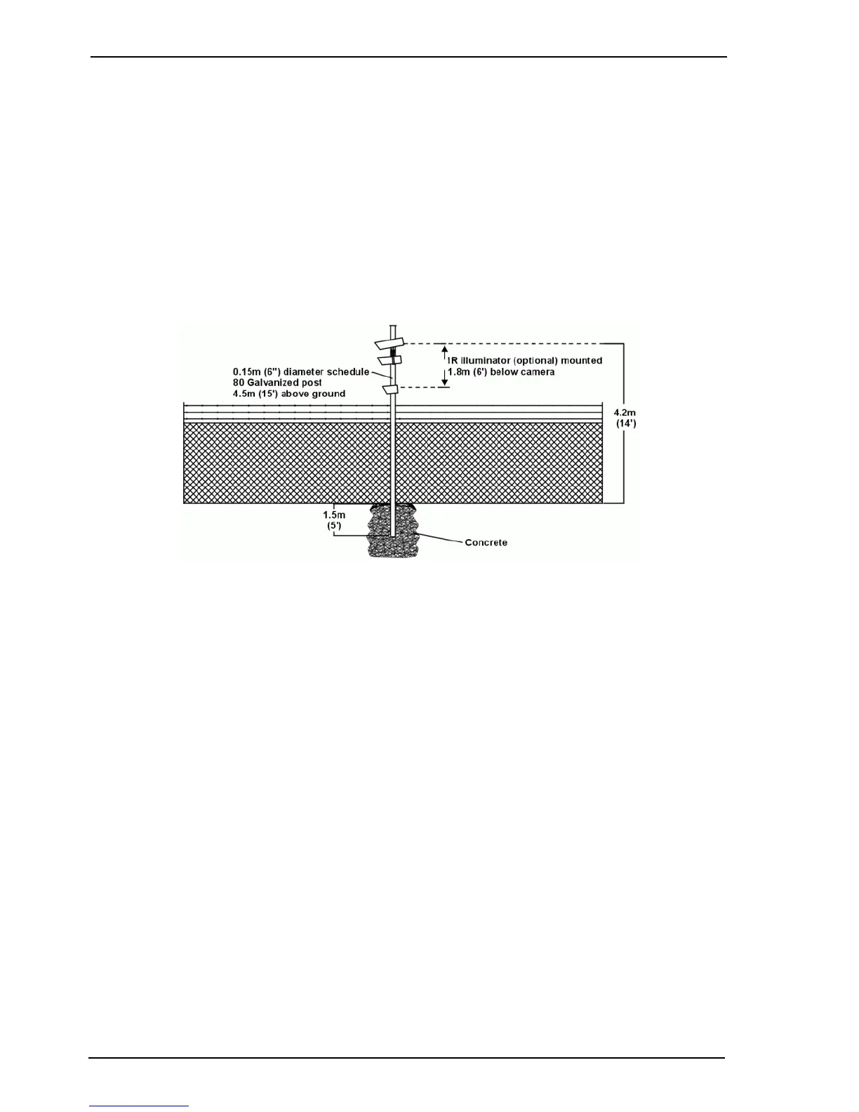
duty mounting location or pole. The following figure shows a typically recommended
mounting pole for a camera/PIR combination as well as infra-red illuminator.
Figure 6: Recommended Presidium Pole Installation
• The position of the cameras relative to lighting is extremely important. Do not install
cameras close to lights (particularly infrared illuminators) which could attract insects, or face
cameras into lights, windows, the sun, or in areas which have a large number of reflections
or shadows. When the lighting is below or to the side of the camera, the recommended safe
distance is 2 metres (6 feet).
• If the lighting is directly above the camera, then insects flying up towards the light in front of
the camera may cause nuisance alarms or obscure the view. If this is the case, ensure that
the lighting is well above the camera, in excess of 4m. The previous image of the pole
shows the location of an IR illuminator. The figure below shows this in greater detail.



 To Next Page