Installation and User Manual ADPRO Presidium by Xtralis
38 Doc. 12384_05
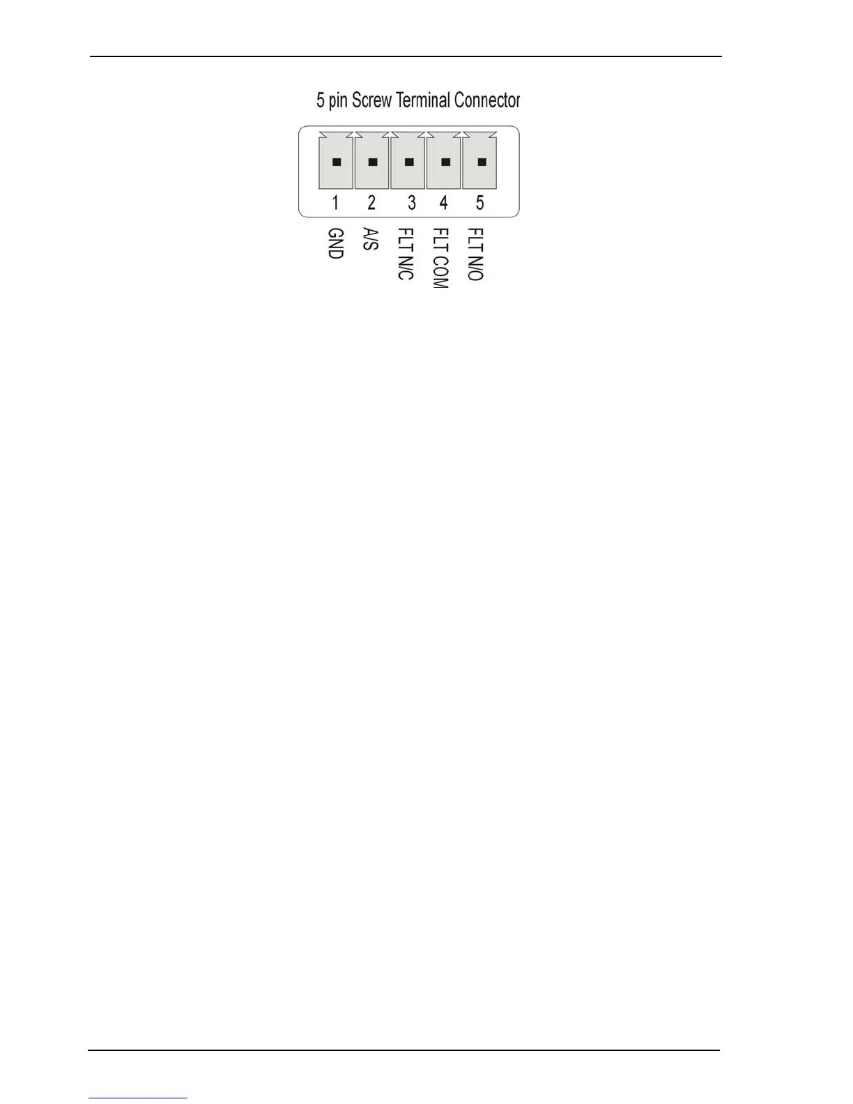
Figure 29: Pinouts for Presidium Mini I/O connector
3.9.1 Access/Secure Input
The Access/Secure input (pin 2) is used to put the Presidium into the Access or Secure state.
When in the Access state, alarm triggers are disabled for alarm inputs and VMD, however alarm
input tamper, contrast, and no-video triggers are still enabled (unless disabled by the Alarm
Isolate). When in the Secure state, all alarm triggers are enabled (unless otherwise disabled by
the Alarm Isolate). The Fault Relay is not affected by this state.
The Access/Secure input allows the Presidium to be independently set into the Access state of
operation. This input is usually connected to an alarm panel or access control system.
The access/secure input is tamper protected (regardless of the access/secure state).
Note: If a tamper is generated on the Access / Secure input then all Presidium channels
will send an alarm.
When connected to a FastTrace / FastTx / FastTrace-R or third party DVR, the Access/Secure
input must be set to Secure. The state is then controlled by the connected DVR.
The Access/Secure Input state may be:
• Normally Open - No End Of Line (NEOL) Resistor
• Normally Closed
• Normally Open SEOL - Single End Of Line Resistor
• Normally Closed SEOL
• Normally Open DEOL - Dual End Of Line Resistor
• Normally Closed DEOL.