ADPRO Presidium by Xtralis Installation and User Manual
Doc. 12384_05 63
Note: The above thresholds may also be displayed in feet (depending on the selection
made in Camera Calibration / Display Units).
1. Once the Detection Parameters have been defined, select Next. The following screen is
displayed.
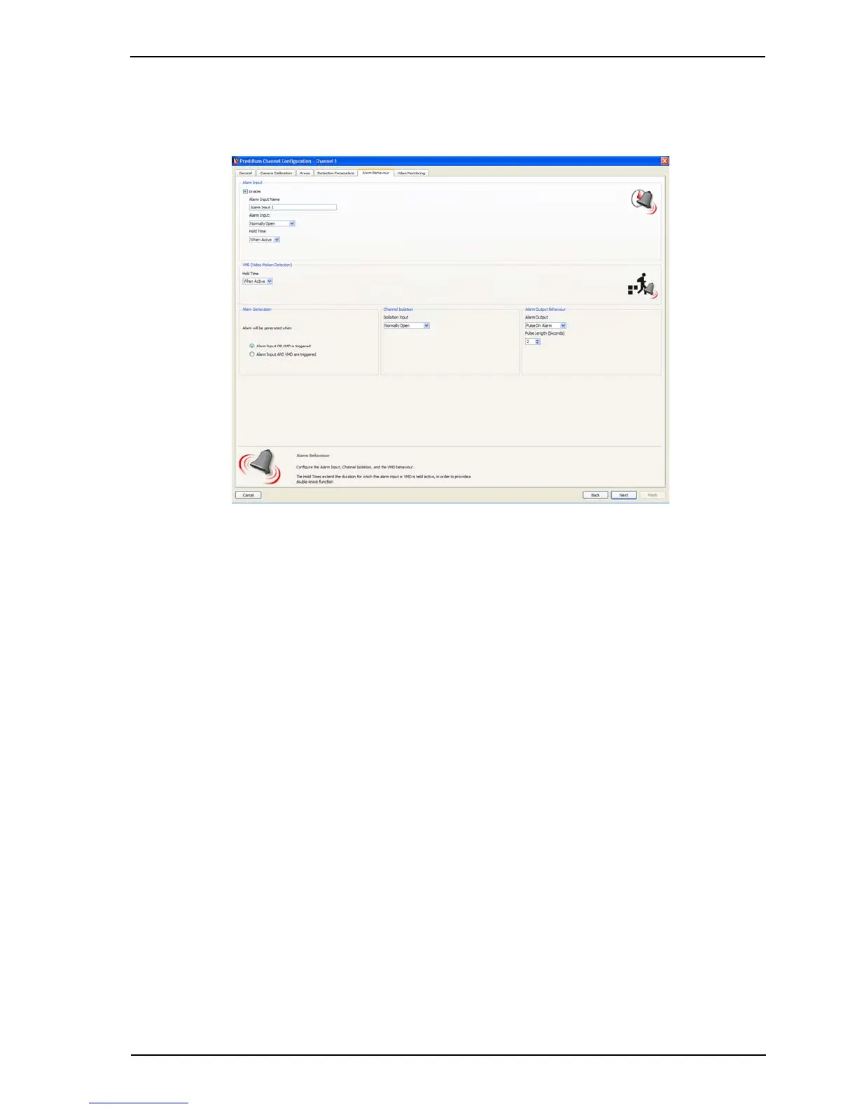
Figure 53: Alarm Behaviour
Alarm Behaviour
The Alarm Behaviour screen enables the configuration of the alarm input, VMD behaviour and
channel isolation.
Alarm Input
1. Check the Enable checkbox if a second detection technology/device (e.g. PIR, microwave
detector or fence sensor) is connected to this channel.
2. Enter a descriptive name for the alarm input in the Alarm Input Name box. This name is
displayed on the Setup screen, but is not communicated to a FastTrace / FastTx /
FastTrace-R or VideoCentral (if connected).
3. Select the type of the Alarm Input:
- Normally Open - No End Of Line (NEOL) Resistor
- Normally Closed
- Normally Open SEOL - Single End Of Line Resistor
- Normally Closed SEOL
- Normally Open DEOL - Dual End Of Line Resistor
- Normally Closed DEOL.
4. Select the required Hold Time for the alarm input.
The Hold Time determines the length of time that a triggered alarm input is active when being
ANDed with VMD to generate an alarm (double-knock method). The Hold Time commences
when the alarm input has stopped triggering. A VMD alarm must be triggered within the Hold
Time for an alarm to be generated.
Any tamper condition on the alarm input will generate an alarm and activate the general alarm
relay.
Note: An alarm input or input tamper alarm will not be generated if the channel is isolated.