ADPRO Presidium by Xtralis Installation and User Manual
Doc. 12384_05 37
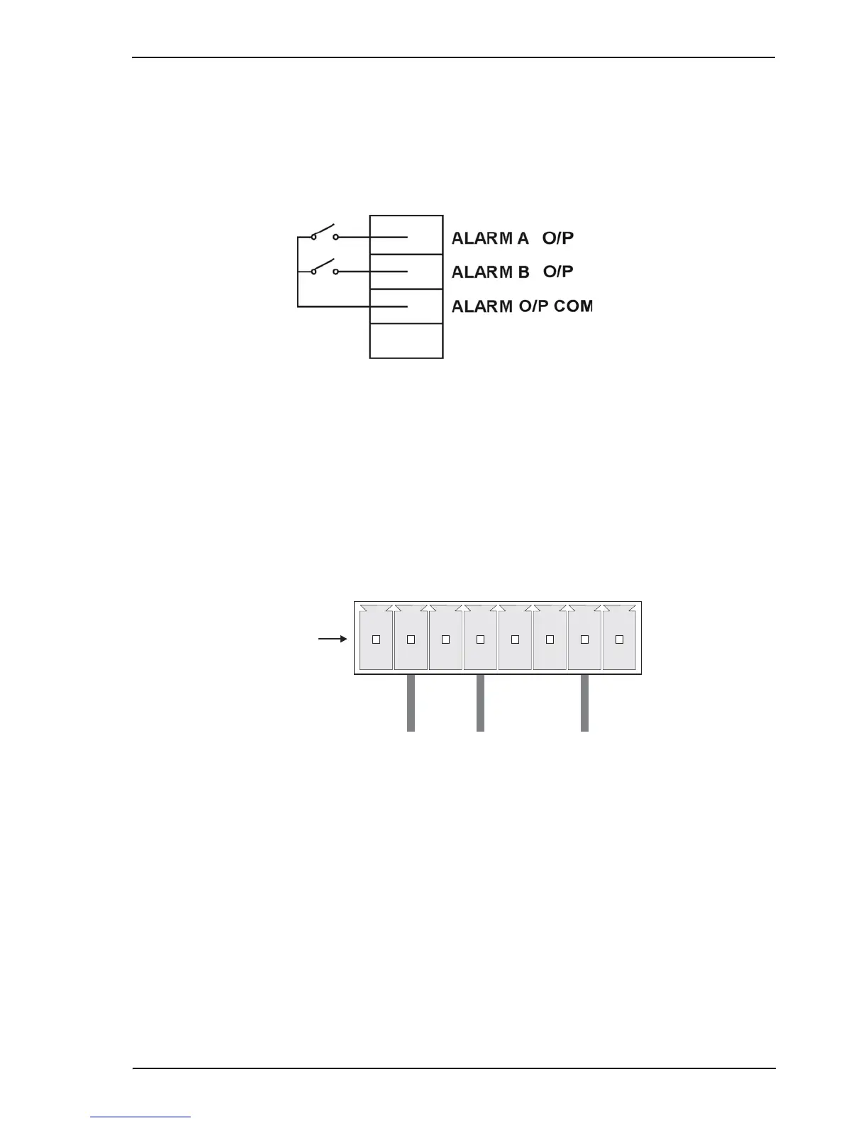
3.8 Alarm Outputs
There are alarm outputs provided for each video channel on a VM15 module or Presidium Mini
and labelled ALM A O/P and ALM B O/P. Alarm outputs may be used to connect the Presidium
to third party alarm panels / DVRs etc.
The alarm outputs are normally open. When in an alarm state, the alarm outputs are closed.
Figure 27: Alarm Outputs
Alarm output relay activates on the occurrence of an intrusion alarm or tamper condition.
All outputs on the alarm connector share a common ground.
3.9 General I/O Connector
To ensure the best immunity to EMC disturbances, the connections on the general I/O connector
should be wired using shielded cable. Connect the shield to the ground (GND) terminal.
Figure 28: Pinouts for Presidium General I/O Connector