ADPRO Presidium by Xtralis Installation and User Manual
Doc. 12384_05 29
3 Presidium Connectors
3.1 Presidium
The standard Presidium is housed in a DIN4194 (Eurocard) standard 3U high subrack unit. It is
designed to be mounted horizontally in a standard 19 inch rack.
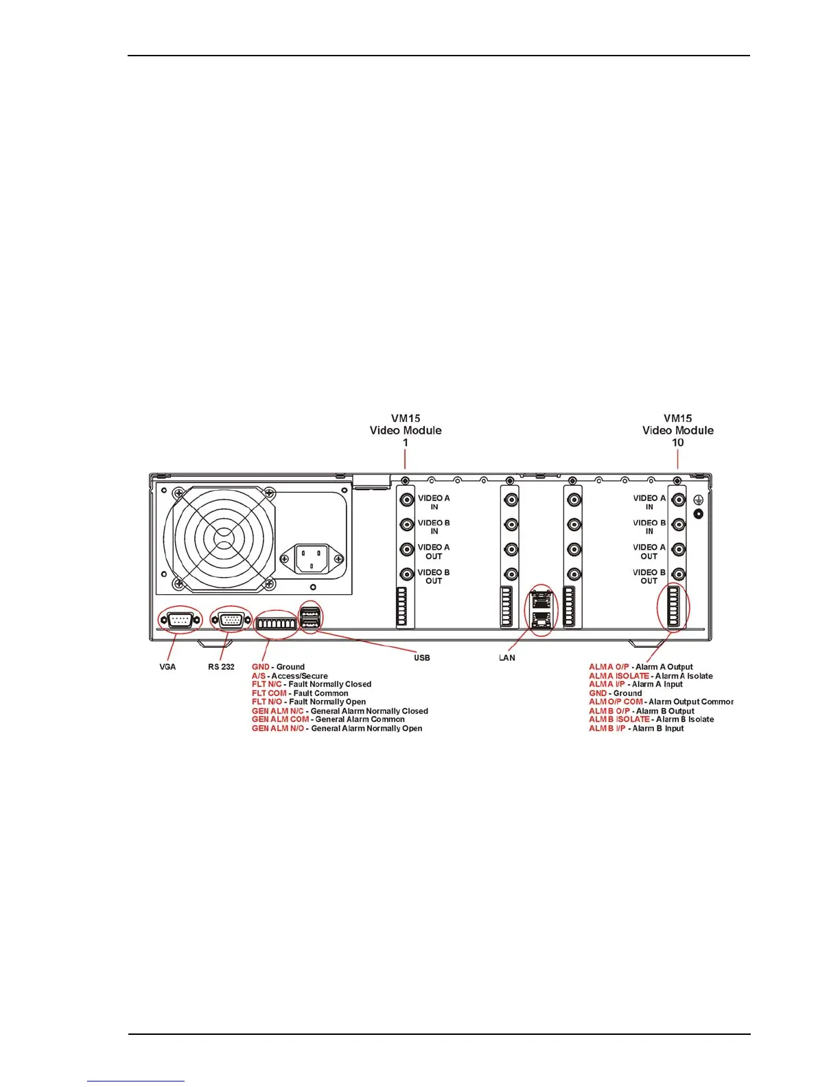
Referring to Figure 19, the Presidium may be configured with the following modules:
• From one to ten VM15 Video Modules may be installed in Video Module slots 1 to 10,
depending on the number of video movement detection channels required. Each VM15
Video Module provides video movement detection for two channels (cameras). Extra VM15
Video Modules may be retro-fitted to provide a maximum of 20 channels per Presidium
(refer to Adding a VM15 Module on page 87). VM15 Modules must be added in order, i.e.
slot 1 first, followed by slot 2 etc, to ensure that camera numbers are correct.
• Each VM15 Video Module incorporates Alarm Input Connectors, one per channel. This
enables alarm sensors (e.g. Passive Infra-Red (PIR), microwave etc.) to be associated with
cameras.
Figure 19: Rear View of the Presidium
Note: The VGA, RS232 and USB ports are currently not used.