ADPRO Presidium by Xtralis Installation and User Manual
Doc. 12384_05 33
.
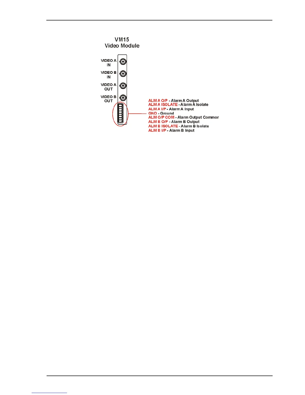
Figure 24: Connection to the VM15 Video Module
In order to synchronise to the incoming video from the camera and to avoid reduced
performance of the video movement detection, the following conditions must be met:
• the sync amplitude at the Video Input of each VM15 Video Module must be within the range
of 0.2 V to 0.4 V, and
• the video amplitude (not including sync) at the Video Input of each VM15 Video Module
must be within the range of 0.5 V to 1.0 V.
If the video level at the Video Input is poor, cable compensators, or video line drivers, should be
installed at the camera end. This boosts the video signal to within the voltage limits given above.
A video contrast level indicator may be displayed on the Presidium video output, if required, to
assist with setting the video contrast levels. Refer to Display All Tracks on Video Output on
page 54 for more information.
3.5.2 Outputs
There are two video outputs on each VM15 Video Module and on Presidium Mini:
• Video A Out; and,
• Video B Out.
The video outputs provide standard composite video signals when driving 75 ohm loads.
In the event of a power failure at the Presidium, the video input signal is passed directly through
from the video input to the video output.