ADPRO Presidium by Xtralis Installation and User Manual
Doc. 12384_05 35
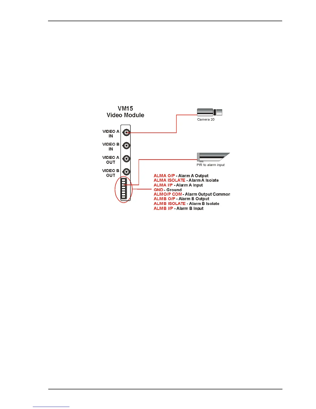
3.6 Alarm Inputs
There are two alarm inputs (one per channel) on each VM15 Video Module and two in total on
Presidium Mini. They are labelled ALM A I/P and ALM B I/P.
The alarm inputs may be used to connect PIRs etc to combine with the video motion detection,
by ‘ANDing’ or ‘ORing’, to generate an alarm. A triggered alarm input may be configured with a
‘hold time’ from 0 to 60 seconds for alarm generation with VMD (refer to Alarm Behaviour on
page 63).
To ensure the best immunity to EMC disturbances, the alarm inputs should be wired using
shielded cable. Connect the shield to the ground (GND) terminal.
Figure 25: PIR Connections (VM15 shown)
The Alarm Input state may be:
• Normally Open - No End Of Line (NEOL) Resistor
• Normally Closed
• Normally Open SEOL - Single End Of Line Resistor
• Normally Closed SEOL
• Normally Open DEOL - Dual End Of Line Resistor
• Normally Closed DEOL.