ADPRO Presidium by Xtralis Installation and User Manual
Doc. 12384_05 87
7 Adding a VM15 Module
Extra VM15 Video Modules may be retro-fitted to provide a maximum of 20 channels per
Presidium.
Caution: ADPRO Presidium system components contain electrical parts that are susceptible
to damage from static discharge. Static voltages of one to thirty kilovolts are
common in unprotected environments.
When installing or servicing Presidium equipment, it is advisable to observe the following
standard precautions for handling electronic assemblies to reduce the risk of component
damage:
• Minimise handling of electronic assemblies and components.
• Transport, temporarily arrange and store electronic components in recognised anti-static
containers.
• Discharge any static voltage from your body before handling electronic components or wear
a grounded, Safety-Standard Approved, anti-static wrist strap while handling components.
• Avoid handling electronic components in areas which have a floor or work-surface capable
of generating a static charge.
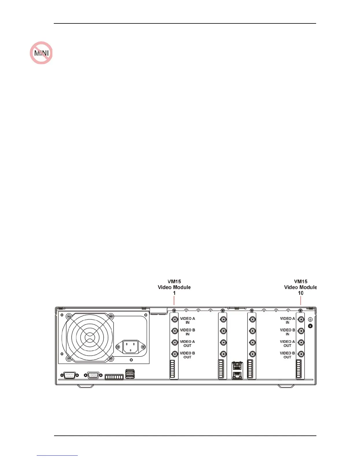
To add a VM15 Module:
1. Ensure that the Presidium is switched off and all power is removed.
2. Remove the 10 screws securing the lid to the top of the Presidium, retaining the screws.
3. Remove the blanking plate from the slot where the new module will be inserted, retaining
the screw.
Note: The module must be inserted into the next blank space, i.e. closest to the mains
power connector.
4. Insert the module, ensuring correct polarity and that the pins are not bent or damaged.
5. Attach the VM15 module to the frame of the Presidium, using the retained blanking plate
screw.
6. Re-attach the lid of the Presidium, using the 10 screws.
Figure 79: VM15 Module Installation