SERVICE POINTS
NOTE:
Cylinder head maintenance is possible
with the power unit mounted.
Cylinder head removal
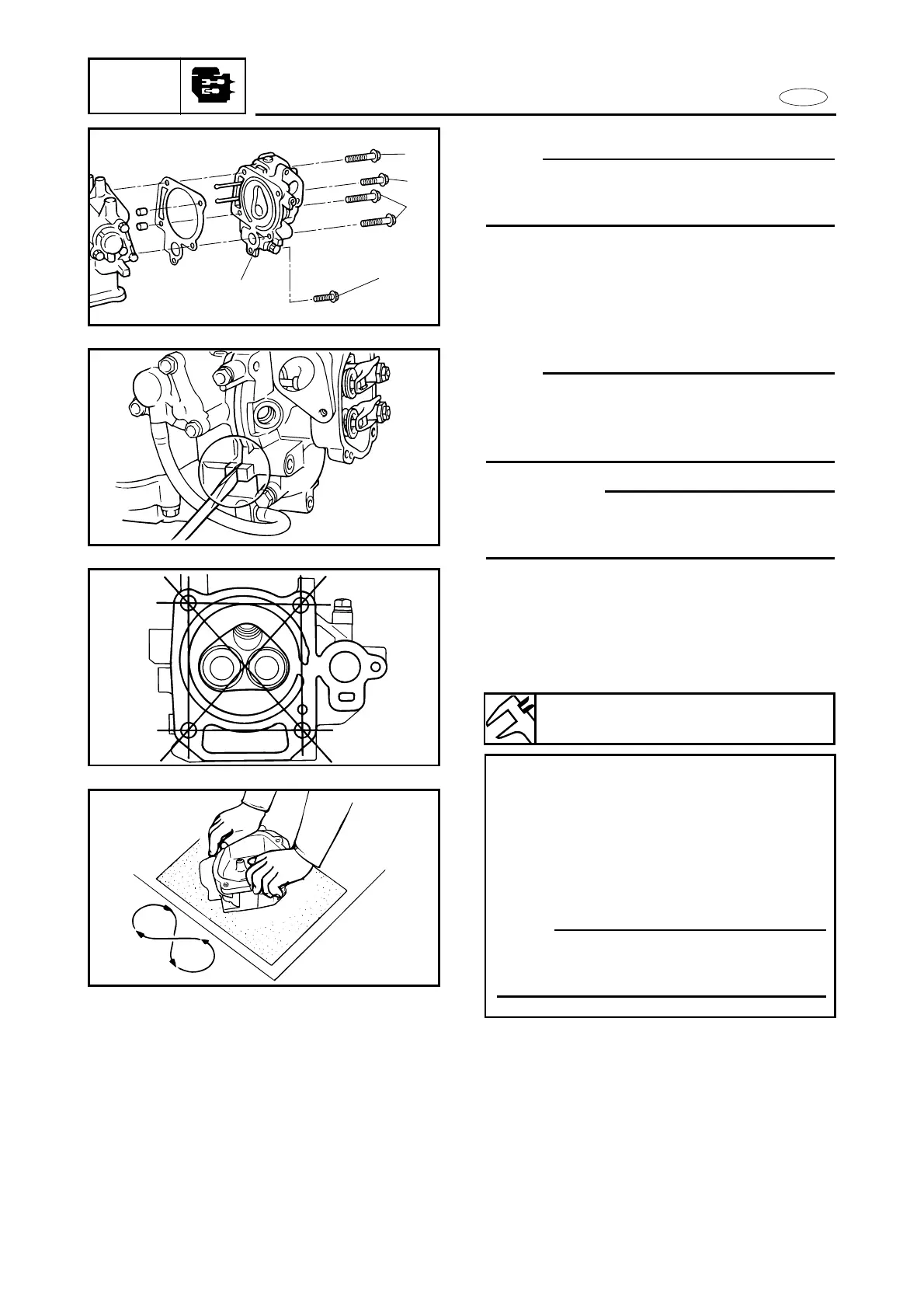
1. Remove:
9Bolt 1 (M6 x 45 mm)
9Bolt 2 (M8 x 60 mm x 3)
9Bolt 3 (M8 x 40 mm x 1)
9Cylinder head 4
NOTE:
Insert a flat-head screwdriver between the
tabs on both side of the cylinder and cylin-
der head and pry open the two parts.
cC
Do not scratch the interface of cylinder
and cylinder head.
5-13
Warpage limit:
0.1 mm (0.004 in)
Resurfacing steps:
8 Place a 400 ~ 600 grit wet sandpaper
on the surface plate.
8 Resurface the cylinder head using a
figure-eight sanding pattern.
To ensure an even surface, rotate the
cylinder head several times.
NOTE:
To ensure an even surface, rotate the
cylinder head several times.
Cylinder head inspection
1. Measure:
9Cylinder head warpage
Out of specification ® Resurface or
replace the cylinder head.