zFor long transom model
9
10
14
11
12
5
4
3
2
1
8
7
6
10 Nm (1.0 m•kg, 7.2 ft•lb)
11
13
17
16
15
M6 x 40 mm
M6 x 167 mm
15
M6 x 16 mm
14
1st 3 Nm (0.3 m•kg, 2.17 ft•lb)
2nd 8 Nm (0.8 m•kg, 5.8 ft•lb)
1st 3 Nm (0.3 m•kg, 2.17 ft•lb)
2nd 8 Nm (0.8 m•kg, 5.8 ft•lb)
6-1
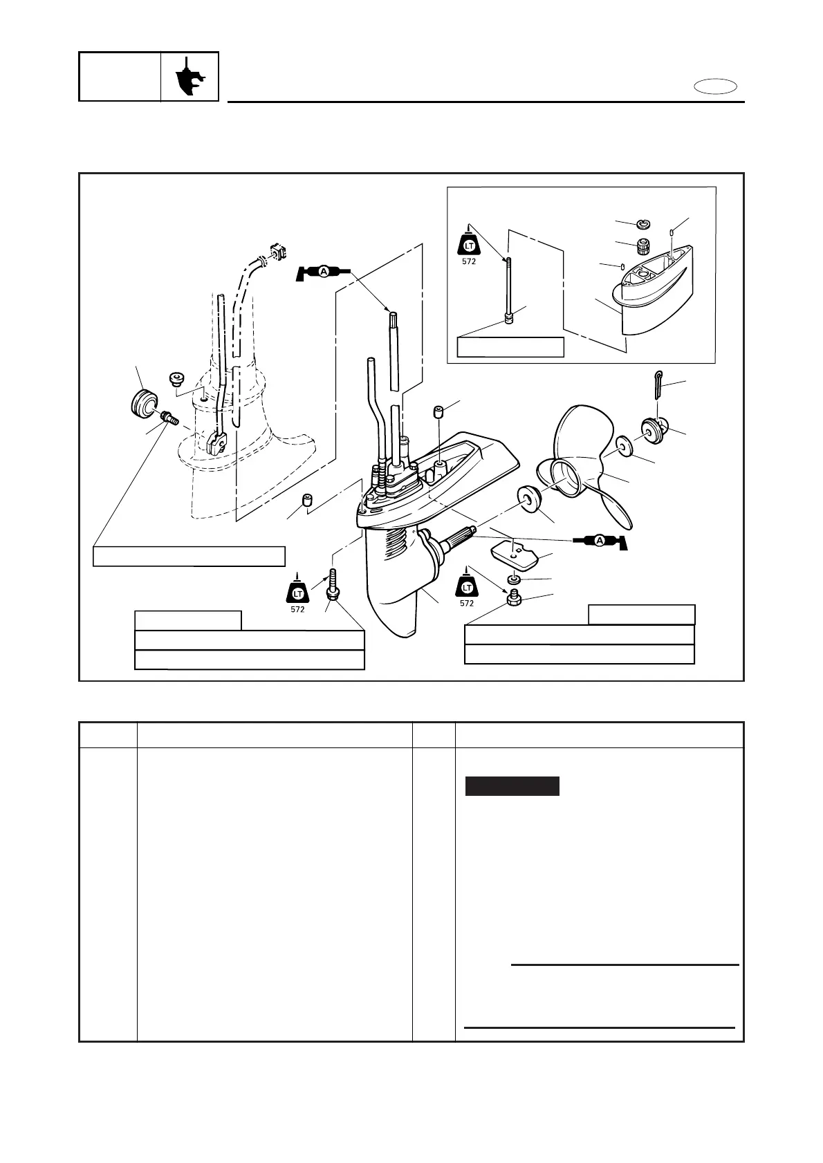
REMOVAL AND INSTALLATION CHART
Step
1
2
3
4
5
6
7
8
9
10
Q’ty
1
1
1
1
1
1
1
1
1
1
Service points
Follow the left “Step” for removal.
NOTE
Set the shift lever to reverse position,
and loosen the bolt (shift rod connec-
tor).
Not reusable
Procedure/Part name
LOWER UNIT REMOVAL
Cotter pin
Propeller nut
Washer
Propeller
Spacer
Bolt (anode)
Toothed washer (anode)
Anode
Grommet
Bolt (shift rod connector)