zFor long transom model
9
10
14
11
12
5
4
3
2
1
8
7
6
10 Nm (1.0 m•kg, 7.2 ft•lb)
11
13
17
16
15
M6 x 40 mm
M6 x 167 mm
15
M6 x 16 mm
14
1st 3 Nm (0.3 m•kg, 2.17 ft•lb)
2nd 8 Nm (0.8 m•kg, 5.8 ft•lb)
1st 3 Nm (0.3 m•kg, 2.17 ft•lb)
2nd 8 Nm (0.8 m•kg, 5.8 ft•lb)
6-2
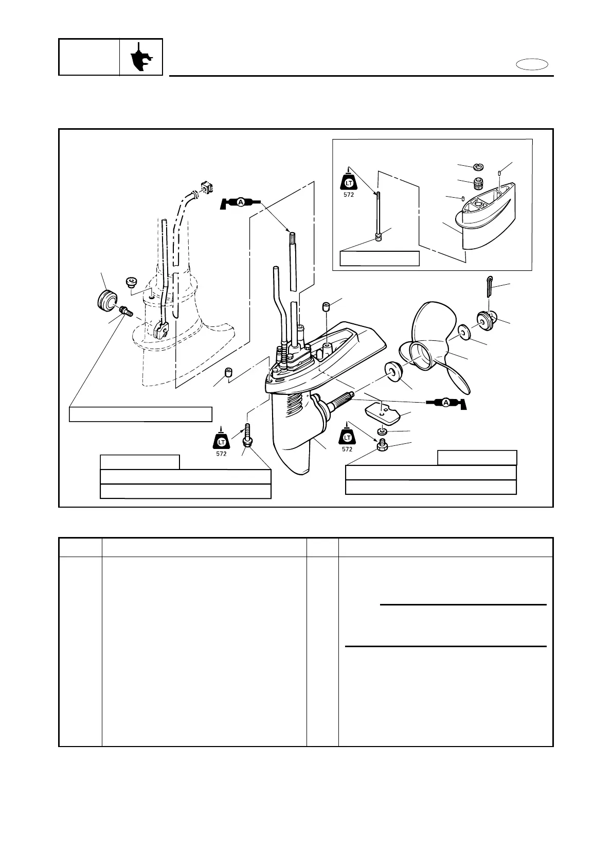
REMOVAL AND INSTALLATION CHART
Step
11
12
13
14
15
16
17
Q’ty
2
1
1
2
2
1
1
Service points
For S-transom model
*For L-transom model
NOTE:
When removing,screw out the bolt
(rear) from upper case and remove the
lower unit with extension.
For L-transom model
For L-transom model
Reverse the removal steps for installation.
Procedure/Part name
Bolt with washer (lower unit)
Lower unit ass‘y
Lower unit with extension
Dowel pins
Dowel pins
Circlip
Bushing