49
MOTIF XS6/MOTIF XS7/MOTIF XS8
Master strings
(マスターストリング)
Slave strings
(スレーブストリング)
Sensor sheet holder
(センサーシートホルダー)
Slave strings
(スレーブストリング)
PC sensor spring
(PCセンサーバネ)
(PCセンサーバネ)(センサーシートホルダー)
PC sensor spring
(スリット)
Slit
GHDPC
Sensor sheet holder
[P60B]
:.@
GHDPC
(PCセンサーバネ)
PC sensor spring
(センサーシートホルダー)
(中継束線3PIN)
Sensor sheet holder
3PIN connector assembly
Keyboard assembly
(HEDafEBUS鍵盤)
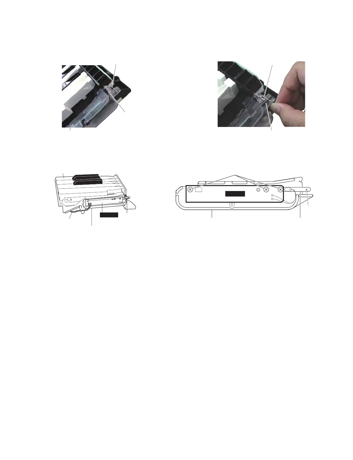
21c Installing the PC Sensor
21c-1 Fit the GHDPC circuit board to the projection of
the sensor sheet holder. (Fig. 23)
21c-2 Attach the three (3) screws marked [P60B] in the
order shown in the fi gure. (Fig. 23)
21c-3 Connect the 3PIN connector assembly to the GH-
DPC circuit board. (Fig. 22)
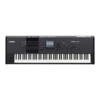
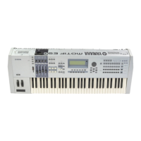
21c-4 Insert the slave strings into the slit of the PC sen-
sor spring. (Photo 10, Photo 11, Fig. 23)
Check that the slave strings can be moved
smoothly by moving the PC sensor spring with
your fi ngers lightly then.
21c-5 Insert the slave strings into the slit of the V-spring
assembly. (Photo 8, Photo 9) Check that the
V-spring assembly can be moved smoothly in the
direction of the strings then.
21c-6 Remove the jig (screw: VB299400).
Fig.22( 図 22)
Photo10( 写真 10) Photo11( 写真 11)
21c PCセンサーの取付け
21c-1 センサーシートホルダーの突起に GHDPC シート
をはめ込みます。(図 23)
21c-2 [P60B] のネジ 3 本を、図で示す順番どおりに取り
付けます。(図 23)
21c-3 中継束線 3PIN を GHDPC シートに接続します。
(図 22)
21c-4 スレーブストリングを、PCセンサーバネのスリッ
トに挿入します。(写真 10、写真 11、図 23)
このとき PC センサーバネを指で軽く動かし、ス
レーブストリングがスムーズに動くことを確認し
ます。
21c-5 スレーブストリングを、V バネ Assy のスリット
に挿入します。(写真 8、写真 9)このとき V バネ
Assy が、ストリングの方向に沿ってスムーズに
動くことを確認します。
21c-6 治具(ネジ:VB299400)を外します。
Fig.23( 図 23)
[P60B]:BindHeadTappingScrew-P(P タイト+ BIND)3.0X8MFZN2B3(WF266600)

 Loading...