MOTIF XS6/MOTIF XS7/MOTIF XS8
18
(パネル支持金具)
Panel holder
Insert into 2 holes
Control panel assembly
(コンパネAssy)
<Right side view>
(2箇所差し込み)
2
1
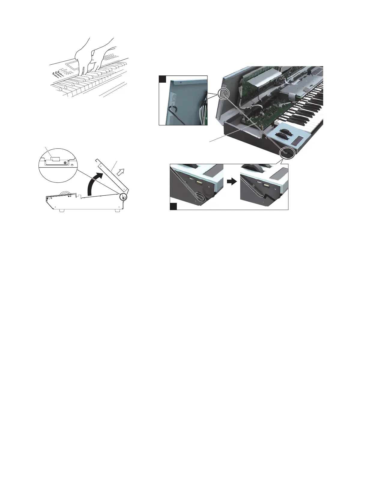
Installing the service stay
(ステイの取り付け方)
1.ステイの先端をシールド板 L の切り込みに挿入し、切り込みの奥で引っ掛けます。
2.コンパネ Assy の A 部にステイを掛けます。
1. Insert the end of the stay into the slot of the shield plate L and engage the stay at the end of the slot.
2. Make the other end of the stay in engagement with the portion A of the control panel assembly.
A
Service stay (V6295700)
(サービス用ステイ)
2-4
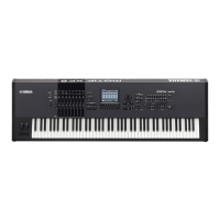
Insert your fi ngers under the middle portion of the
control panel assembly and open to the position
shown in Fig. 3 and then pull the control panel
assembly in the direction of the white arrow in Fig. 3.
(Fig. 2, 3)
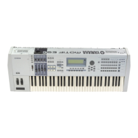
*
When installing the control panel assembly, tilt
the control panel assembly as shown in Fig. 3 and
insert the panel holders into the two holes. (Fig. 3)
* When closing the control panel assembly, take
care not to pinch connector assemblies.
3. JKAN-JA Circuit Board
(Time required: About 4 minutes)
3-1 Remove the side panel R and side panel L. (See
procedure 1.)
3-2 Open the control panel assembly (see procedure 2)
and use the service stay (V6295700) to make the
panel secured. (Photo 1)
3-3 Remove the nine (9) screws marked [370], the
screw marked [385] and two (2) screws marked
[390]. The JKAN-JA circuit board can then be
removed. (Fig. 4)
4. DM Circuit Board
(Time required: About 4 minutes)
4-1 Remove the side panel R and side panel L. (See
procedure 1.)
4-2 Open the control panel assembly. (See procedure
3-2.)
4-3 Remove the connector assembly from the cable
clamp on the DM cover.
2-4 コンパネ Assy の中央部に指を掛けて図 3 の位置
まで開き、コンパネ Assy を図 3 の白矢印の方向
に引き上げて外します。(図 2、図 3)
※ コンパネ Assy を取り付けるときは、コンパネ
Assy を図 3 のように斜めにして、2 個所の穴に
パネル支持金具を差し込んでください。(図 3)
※ コンパネ Assy を閉めるときは、束線を挟まない
よう注意してください。
3. JKAN-JA シート(所要時間:約 4 分)
3-1 サイドパネル R とサイドパネル L を外します。
(1 項参照)
3-2 コンパネ Assy を開き(2 項参照)、サービス用の
ステイ(V6295700)でパネルを固定します。(写真 1)
3-3 [370] のネジ 9 本と [385] のネジ 1 本、[390] のネ
ジ2 本を外して、JKAN-JA シートを外します。(図 4)
4. DM シート(所要時間:約 4 分)
4-1 サイドパネル R とサイドパネル L を外します。
(1 項参照)
4-2 コンパネ Assy を開きます。(3-2 項参照)
4-3 カバー DM 上のケーブルクランプから束線を外し
ます。
Fig.3( 図 3)
Fig.2( 図 2)
Photo1( 写真 1)

 Loading...