Do you have a question about the Yamaha Motif XS Series and is the answer not in the manual?
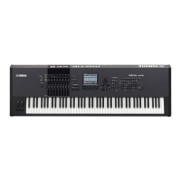
| Type | Workstation Synthesizer |
|---|---|
| Sound Engine | AWM2 with Expanded Articulation |
| Polyphony | 128 notes |
| Wave ROM | 355MB (when converted to 16-bit linear format) |
| Arpeggiator | 6, 000 types |
| Effects | Reverb, chorus, part EQ |
| Sequencer | 16-track sequencer, 130, 000 notes |
| Display | 320 x 240 dot backlit LCD |
| Connectivity | USB, MIDI In/Out/Thru |
| Storage | USB storage device support |
| Keyboard | 88-key (Motif XS8), 76-key (Motif XS7), 61-key (Motif XS6) |
| Number of Voices | 1, 024 normal voices + 64 drum kits |
Details the types and key counts for MOTIF XS6, XS7, and XS8 models.
Covers sound engine, polyphony, timbral capacity, and voice structure.
Details sampling capabilities, sources, conversion, data bits, frequency, and memory.
Information on note capacity, resolution, polyphony, tempo, tracks, patterns, and songs.
Lists all physical connectors, power consumption, and weight details.
Diagrams and labels for the top panel controls of MOTIF XS6 and XS7.
Identification of all rear panel connectors and controls for MOTIF XS models.
Diagrams illustrating the component placement on MOTIF XS6/XS7 circuit boards.
Diagrams illustrating the component placement on MOTIF XS8 circuit boards.
Important safety and handling notes before disassembling the unit.
Step-by-step guide for removing the side panels.
Procedure for safely removing the main control panel assembly.
Detailed steps for removing the JKAN-JA circuit board.
Detailed steps for removing the DM circuit board.
Detailed steps for removing the JKAN-ML circuit board.
Procedure for removing the power supply and related components.
Detailed steps for removing the display unit.
Procedure for removing the JKAN-LC circuit board and LCD.
Detailed steps for removing the PNA circuit board.
Detailed steps for removing the PNB-PN circuit board.
Detailed steps for removing the PNC circuit board.
Procedure for removing end block R and PNB-RB circuit board.
Detailed steps for removing the end block L and touch volume.
Important safety and handling notes before disassembling the unit.
Step-by-step guide for removing the side covers.
Procedure for safely removing the main control panel assembly.
Detailed steps for removing the JKAN-JA circuit board.
Detailed steps for removing the DM circuit board.
Procedure for removing JKAN-ML and MLAN circuit boards.
Procedure for removing the power supply and related components.
Detailed steps for removing the display unit.
Procedure for removing the JKAN-LC circuit board and LCD.
Detailed steps for removing the PNA circuit board.
Detailed steps for removing the PNB-PN circuit board.
Detailed steps for removing the PNC circuit board.
Procedure for removing arm assembly R and end block R.
Detailed steps for removing the arm assembly L.
Detailed steps for removing the front rail assembly.
Detailed steps for removing the rear panel.
Procedure for disassembling the keyboard assembly.
Detailed steps for removing the GHDPC circuit board.
Procedure for replacing the PC sensor component.
Procedure for replacing the string set components.
Detailed steps for disassembling the keyboard assembly.
Detailed steps for removing rubber contacts.
Procedure for removing white keys from the keyboard.
Step-by-step instructions for installing the mLAN expansion board.
Guide on installing DIMM memory modules, including compatible types.
Detailed pin descriptions for the CPU (USB) LSI.
Detailed pin descriptions for the SRC16 (Gate Array) LSI.
Detailed pin descriptions for the MCI (Gate Array) LSI.
Detailed pin descriptions for the ADC (Analog to Digital Converter) LSI.
Detailed pin descriptions for the DICEII LSI.
Detailed pin descriptions for the SWP51 (Tone Generator) LSI.
Detailed pin descriptions for the USB2.0 Host Controller LSI.
Detailed pin descriptions for the E-LKS LSI.
Detailed pin descriptions for the LED Driver/Switch Scan LSI.
Detailed pin descriptions for the PHY LSI.
Detailed pin descriptions for the E-VKS LSI.
Detailed pin descriptions for the DAC (Digital to Analog Converter) LSI.
Detailed pin descriptions for the LCD Controller LSI.
Block diagram for the SN74AHCT04PWR Hex Inverter IC.
Block diagram for the HD74LVC08TELL Quad 2 Input AND IC.
Block diagram for the TC74VHC14FT(EL,K) Hex Inverter IC.
Block diagram for the HD74LV21ATELL Dual 4 Input AND IC.
Block diagram for the TC7VHCT32AFT-EL Quad 2 Input OR IC.
Block diagram for the TC7LCX74FT(EL,K) Dual D-Type Flip-Flop IC.
Block diagram for the HD74LV125ATELL Quad 3-State Bus Buffer IC.
Block diagram for the HD74LVC139TELL-E Demultiplexer IC.
Block diagram for the HD74LVC244ATELL Octal 3-State Bus Buffer IC.
Information on preparing for manual and MIDI mode tests.
How to enter MANUAL MODE and MIDI MODE for tests.
Guidance on executing tests in MANUAL and MIDI modes.
Procedures for handling tests that result in NG.
Explanation of how A/D values are displayed during tests.
Instructions on how to access the hidden updater mode.
Steps for navigating and operating in the File mode.
Instructions on how to create a new directory for file storage.
Guide to saving all user data or specific data types.
Procedure to restore the synthesizer to its original factory default settings.
Configuration for automatically restoring factory settings on power-on.
Instructions for inserting the USB flash memory with the update file.
Steps to enter the unit into firmware update mode.
Procedure to verify the installed firmware version.
Diagram illustrating the MIDI transmit flow for synthesizer/sequencer parts.
Diagram illustrating the MIDI receive flow for the synthesizer.
Exploded view and parts list for MOTIF XS6/XS7 overall assembly.
Exploded view and parts list for MOTIF XS8 overall assembly.
Exploded view and parts list for the bottom assembly of MOTIF XS6/XS7.
Exploded view and parts list for the bottom unit of MOTIF XS8.
Exploded view and parts list for the control panel assembly.
Exploded view and parts list for the MOTIF XS6 FSX keyboard assembly.
Exploded view and parts list for the MOTIF XS7 FSX keyboard assembly.
Exploded view and parts list for the MOTIF XS8 HEDaf EBUS keyboard assembly.
Parts list and diagram for the pitch bend and modulation wheel assembly.
Diagram and parts list for the PNA circuit board.
Diagram and parts list for the PNB-PN circuit board.
Diagram and parts list for the PNC circuit board.
List of electronic components, including circuit boards and their part numbers.